Performance Check! Calibration-P6021
PERFORMANCE CHECK/CALIBRATION
PROCEDURE
General
The following procedure is arranged so that the P6021
Current Probe and Termination can be calibrated with the
least, interaction of adju
s
tm
ents
and reconnection of equip
ment, The equipment
required
for the entire procedure is
shown in Fig. 5-1. Fol
lo
w
i
ng
the picture is a complete list
of control settings for the test equipment.
All
waveforms shown in this procedure were token with
a
Tektronix Oscilloscope Comero System. The following
procedure uses the equipment listed under Test Equ
ipm
ent
Required.
If
eq
u
ip
m
en
t is substituted, control settings or
equipment setup may need to be altered to meet the require
ments of the equipment used. Det
a
iled ope
r
a
t
i
ng instructions
for the test equipment
is
not given in this procedure.
If
in
doubt as to the correct operation of any of the test equip
ment, refer to the instruction manual for that unit.
Preliminary Procedure for Complete Calibration
To eliminate interaction of current probe and termination
adjustments w
h
e
n
p
er
f
o
rmi
n
g
caibration, the probe is ad
justed using a standard 50-ohm termination. However,
a
sp
e
ci
al impedance matching network must be constructed to
match the 62.S-ohm probe coble to the 50-ohm termination.
Usi
n
g a GR insertion unit, construct the network shown
i
n
F
i
g
.
5-2. Mark the insertion unit for direction and place the
cover over the openings.
,------- -,
From
current
probe
GR
InSertiOn
)
unit
To
test
oscilloscope
Fig. 5-2. Impedance matching network constructed in
GR
insertion
unit.
Remove the top cover only from the P6022 Termination.
The snap-on cover may be removed either with the fingers
or
by
placing a small screwdriver between the cover and
the termination, near the part number, and lurning slightly.
The bottom cover must remain in place whenever the te
r
m
i
nation is in use.
Focus
Intensity
5-3
TEST OSCillOSCOPE
Any position
Midrange
Astigmatism
Any position
Scale ilium
As desired
Volts/Cm
.02
Variable Volts/Cm
Cal
Gain
XIO
Input Coupling
DC
T rigger Slope
+
Triggering
Source
Int-AC
Time/Cm
.05
Horizontal
Display
Internal
5X Magnifier
Off
Amplitude
Voltage Range
Pulse Polarity
PULSE GENERATOR
30
50
+
NOTE
Sweep
If completing Performance Check only, do steps
1
a,
1 b,
and
Ie.
Then proceed to step 2.
1.
Adjust Current Probe
a. Connect a 50-ohm GR termination to one of the pulse
generator charge line connectors.
IA)
l
�
IB)
IC)
e22
C25
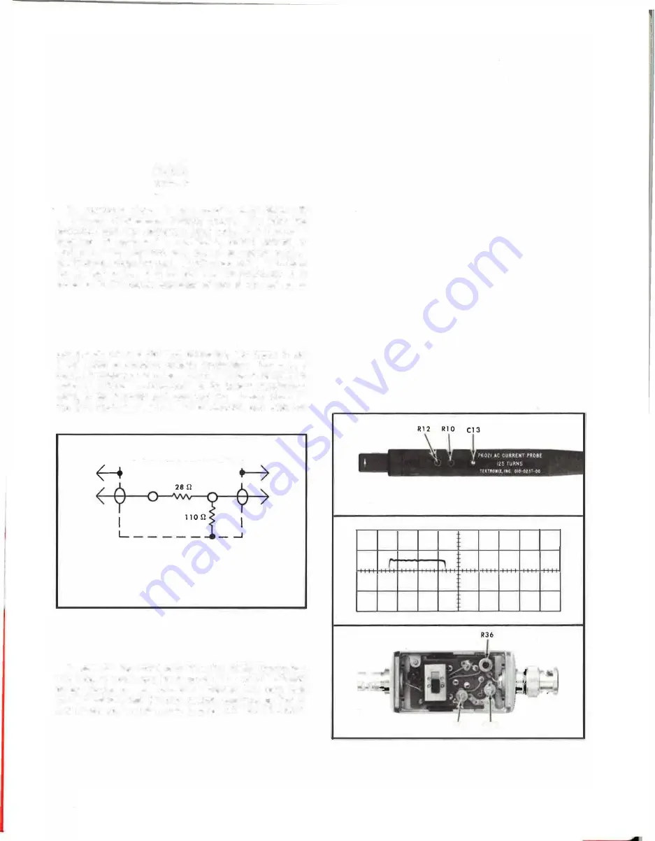
Fig. 5-3. P6021 aberrations, showing
IAI
location of probe ad
justments,
IBI
four-centimeter display of pulse generator output,
and
(C I
location of termination adjustments.


