Load the Filter Software
1.
Insert the CD in the oscilloscope drive.
2.
Navigate to the CD folder and make a copy
of the Socket Cable XL Filter Files.
3.
Paste the
fi
les in C:/TekScope/
Math_Arbitrary_Filters/Probe-Filters.
4.
From the Vertical menu, click Probe Cal.
Under Probe Tip, select Other Tip.
5.
From the Math menu, select Math Setup.
6.
Click Editor and select Filter.
7.
In the user-de
fi
ned Arbitrary Filter area,
click the Load button.
8.
Navigate to the directory that you stored the
fi
lter in (from step 2) and select the
fi
lter.
Using the Filter Software
Two
fi
lters are available:
XL_HTT_DIFF_Multirate.
fl
t
(for differential mode)
XL_HTT_A_B_COMM_Multirate.
fl
t
(for A-Gnd, B-Gnd, and CM modes)
Both
fi
lters are multi-rate
fi
lters that can
operate at sampling rates from 50 GS/s down
to 1.25 GS/s. Since these are multi-rate
fi
lters,
the
fi
lter bandwidth and rise time vary with the
sample rate.
The
fi
lters are 4000 points long, so your
oscilloscope record length must be at least 2X
or greater to display a usable waveform. The
fi
rst and last 2000 points of record length are
truncated from the
fi
ltered waveform.
More information about using
fi
lters is located in
the Tektronix Digital Oscilloscopes Online Help
in the “Math Equation Editor (Filter Tab)” topic.
For speci
fi
c information on arbitrary
fi
lters, refer
to “Arbitrary
fi
lters, math”.
Replacing the Resistors
The resistors that are presoldered to the solder
tips need to be replaced periodically, due to
normal wear. A kit of replacement resistors is
available (order part number 020-2937-00).
1.
Apply a soldering iron to the via on the tip
board and remove the existing wire. Work
quickly with a low-heat soldering iron.
If a small piece of wire is in the via, heat the
solder and use another piece of wire to push
the wire fragment from the via.
2.
Add fresh solder to the via, if necessary.
3.
Cut one lead of the resistor to 0.2" (5mm).
4.
Heat the solder in the via and thread the cut
resistor lead into the via, leaving enough
lead length to bend the resistor
fl
at with the
tip board.
5.
Cut excess lead on the bottom of the board.
6.
Cut the remaining resistor lead as necessary
to reach your test point.
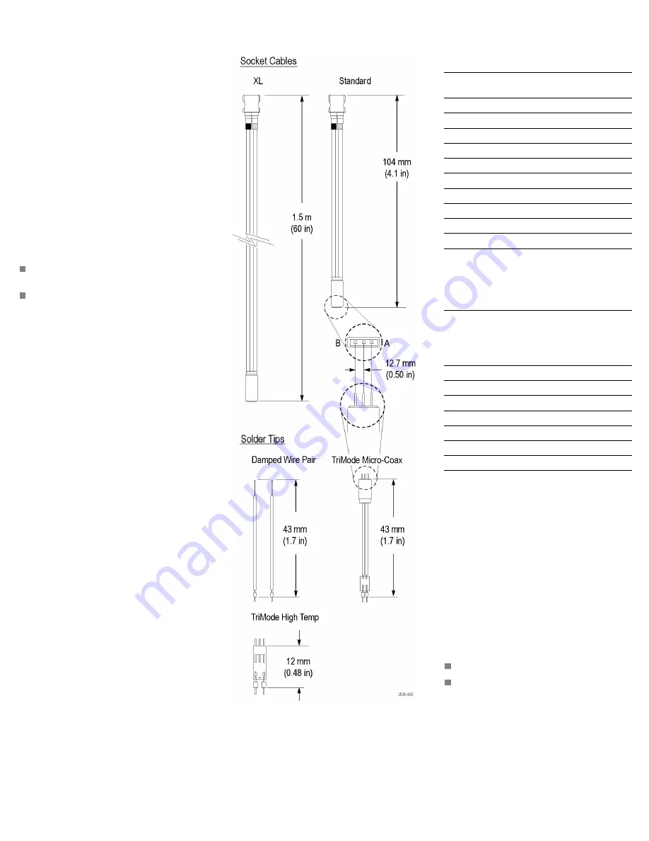
Dimensions
Electrical Characteristics (Typical)
Table 1: Socket Cable
1
Tip/measurement
mode
Rise time, ps
10–90% 20–80%
BW,
GHz
TriMode High Temp Solder Tip
Differential (A-B)
60
40
6
Single-ended (A, B)
120
80
3
Common-mode
150
100
2.5
TriMode Micro-Coax Solder Tip
Differential (A-B)
100
60
4
Single-ended (A, B)
150
100
2.5
Common-mode
200
135
1.5
Damped Wire Pair
Differential (A-B)
50
35
8
1
Temperature range 0 °C to +40 °C (32 °F to 104 °F)
Table 2: Socket Cable XL with TriMode High Temp
Solder Tip and DSP
fi
lter
fi
les
1 2
Measurement mode
Differential
A, B, Com
Acquisition
rate, Gs/s
Rise time,
ps, 10–90%
BW,
GHz
Rise time,
ps, 10–90%
BW,
GHz
50
55
10
150
3
25
60
8
150
3
12.5
120
4
150
3
6.25
230
2
230
2
3.125
450
1
450
1
1.5625
900
0.5
900
0.5
1.25
1150
0.4
1150
0.4
1
The DSP
fi
lter
fi
les must be used with the Socket Cable XL.
2
Temperature range –55 °C to +150 °C (-67 °F to 302 °F)
Warranty Information
For warranty information, go to
www.tektronix.com\warranty.
Contacting Tektronix
Tektronix, Inc.
14200 SW Karl Braun Drive
PO Box 500
Beaverton, OR 97077
USA
For product information, sales, service, and
technical support:
In North America, call 1-800-833-9200.
Worldwide, visit www.tektronix.com to
fi
nd
contacts in your area.
Copyright © Tektronix, Inc. All rights reserved.
www.tektronix.com


