


03
step
TWP-XUT TRANSMITTER TEMPERATURE INPUT CONFIGURATION
21
INSTALLATION GUIDE
PLUS TWP-XUT
NOTE:
By default, temperature inputs are configured as PT100 3W.
Each temperature input can be configured independently, as PT100 ou Thermocouple.
01
To enter in
Configuration Mode
follow steps 01 to 05 of TWP-XUT PLUS Wireless
Transmitter
Configuration
.
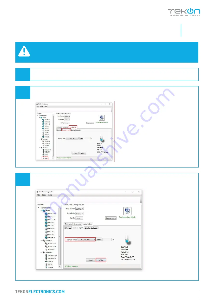
02
In
Tekon Configurator Software
select
PLUS
>>
Transmitter
>>
Sensor Input
menu
2
1
3
03
As an example, select
PT100 4W
option on Sensor Input 1 and click
Write
.
If you are configuring
PLUS TWP-2UT
,
reproduce configuration steps to the
second temperature input.
If you are configuring
PLUS TWP-2UT
,
reproduce configuration steps to the
second temperature input.
Summary of Contents for PA202320110
Page 13: ...02 step TWP XUT PLUS WIRELESS TRANSMITTER CONFIGURATION...
Page 20: ...03 step TWP XUT TRANSMITTER TEMPERATURE INPUT CONFIGURATION...
Page 24: ...04 step TWP XUT TRANSMITTER DIGITAL OUTPUT CONFIGURATION...
Page 27: ...05 step WGW420 GATEWAY ANALOG OUTPUTS CONFIGURATION...
Page 30: ...06 step WRP001 PLUS WIRELESS REPEATER CONFIGURATION...
Page 36: ...07 step SITE SURVEY MODE...


