background image

Step 

 å

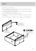
Carefully turn your unit over onto its front edges.

 å

Fasten the ENDS (A and B) to the BRACE (D). Use two BLACK
1-1/2" FLAT HEAD SCREWS (10).

 å

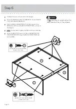
Insert six BACK CONNECTORS (7) into the grooves in the
ENDS (A and B). Space the BACK CONNECTORS as shown in 
the diagram.

 å

NOTE: You may need to gently tap them in with your hammer.

 å

Fasten the BACK (H) to your unit. Use six SILVER 5/8" FLAT
HEAD SCREWS (13) through the BACK CONNECTORS and 
into the ENDS.

Step 6

Page 10

BLACK 1-1/2" FLAT HEAD SCREW

(2 used in this step)

10

D

A

B

Do not stand the unit upright without the 
BACK fastened. The unit may collapse.


Caution

H

7

7

SILVER 5/8" FLAT HEAD SCREW

(6 used in this step)

13

Summary of Contents for Clifton Place 5421116

Page 1: ...www teknikoffice co uk Hutch Clifton Place Collection Model 5421116 NOTE THIS INSTRUCTION BOOKLET CONTAINS IMPORTANT SAFETY INFORMATION PLEASE READ AND KEEP FOR FUTURE REFERENCE For things n such Teknik ...

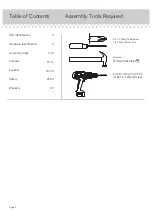
Page 2: ...4 5 14 15 17 18 20 21 22 23 Part Identification Hardware Identification Assembly Steps Français Español Safety Warranty Hammer Not actual size No 2 Phillips Screwdriver Tip Shown Actual Size Page 2 Electric drill with 1 4 bit ONLY in indicated step ...

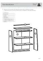
Page 3: ...ked letter on the edge to help distinguish similar parts from each other Use this part identification to help identify similar parts A RIGHT END 1 B LEFT END 1 C TOP 1 D BRACE 1 E MOLDING 2 F UPPER ADJUSTABLE SHELF 1 G LOWER ADJUSTABLE SHELF 1 H BACK 1 Now you know our ABCs Page 3 A B C D E F G H E ...

Page 4: ...CAM SCREW 4 2 APPLIQUE CARD 1 8 WOOD DOWEL 4 3 RUBBER SLEEVE 8 6 METAL PIN 8 5 SHORT WOOD DOWEL 4 4 BLACK 1 1 2 FLAT HEAD SCREW 4 10 BLACK 1 1 8 FLAT HEAD SCREW 6 11 SILVER 5 8 FLAT HEAD SCREW 6 13 BLACK 1 PAN HEAD SCREW 8 12 HIDDEN CAM 4 1 FURNITURE TIPPING RESTRAINT KIT 1 99 BACK CONNECTOR 6 7 BRACKET 2 9 ...

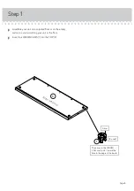
Page 5: ...r or on the empty carton to avoid scratching your unit or the floor å Insert four HIDDEN CAMS 1 into the TOP C Page 5 The arrow in the HIDDEN CAM must point toward the hole in the edge of the board 4 used 1 Arrow C S u r f a c e w i t h g r o o v e ...

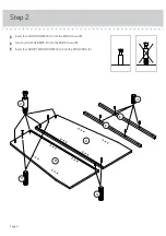
Page 6: ...Step 2 å Insert four WOOD DOWELS 3 into the ENDS A and B å Turn four CAM SCREWS 2 into the ENDS A and B å Insert four SHORT WOOD DOWELS 4 into the MOLDINGS E Page 6 A B E E 3 2 4 3 ...

Page 7: ...TOP C Use six BLACK 1 1 8 FLAT HEAD SCREWS 11 å NOTE Be sure the SHORT WOOD DOWELS in the MOLDINGS insert into the TOP Step 3 Page 7 Groove E E C BLACK 1 1 8 FLAT HEAD SCREW 6 used in this step 11 Remember Righty tighty Lefty loosey ...

Page 8: ... the LEFT END inserts into the TOP å Unfold the BACK H and slide the BACK into the grooves in the TOP C and LEFT END B Page 8 C Groove C B H B 1 2 Do not stand the unit upright without the BACK fastened The unit may collapse Caution NOTE Position the BACK exactly as shown Finished surface without tape ...

Page 9: ...BACK inserts into the groove in the BRACE å Fasten RIGHT END A to the TOP C Tighten two HIDDEN CAMS å NOTE Be sure the BACK inserts into the groove in the RIGHT END å NOTE Be sure the WOOD DOWELS in the RIGHT END insert into the TOP and BRACE Step 5 Page 9 C A Groove D B Groove ...

Page 10: ...ONNECTORS as shown in the diagram å NOTE You may need to gently tap them in with your hammer å Fasten the BACK H to your unit Use six SILVER 5 8 FLAT HEAD SCREWS 13 through the BACK CONNECTORS and into the ENDS Step 6 Page 10 BLACK 1 1 2 FLAT HEAD SCREW 2 used in this step 10 D A B Do not stand the unit upright without the BACK fastened The unit may collapse Caution H 7 7 SILVER 5 8 FLAT HEAD SCRE...

Page 11: ...e fastening the Hutch to the Library Base Top å The following steps show the Hutch being fastened to the Library Base å Finish drilling the two holes shown in the bottom surface of the Library Base Top using a 1 4 drill bit Follow the diagram å Next fasten the Library Base Top to the ENDS A and B Use two BLACK 1 1 2 FLAT HEAD SCREWS 10 Page 11 Finish drilling these two holes from the bottom surfac...

Page 12: ...ssembly Tighten six HIDDEN CAMS å NOTE Be sure the WOOD DOWELS in the Library Base Top insert into the Library Base å NOTE If needed follow the 421114 or 421115 instruction book to finish the assembly of the Lateral File or Library Base Step 8 Page 12 L i b r a r y B a s e T o p ...

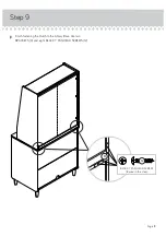
Page 13: ...Step Step 9 å Finish fastening the Hutch to the Library Base Use two BRACKETS 9 and eight BLACK 1 PAN HEAD SCREWS 12 Page 13 9 BLACK 1 PAN HEAD SCREW 8 used in this step 12 ...

Page 14: ...tions of your choice in the ENDS A and B Set the ADJUSTABLE SHELVES F and G onto the METAL PINS å Peel the STICKERS from the APPLIQUE CARD 8 and stick one onto each visible HIDDEN CAM and SCREW å NOTE Please read the back pages of the instruction booklet for important safety information å This completes assembly Clean with your favorite furniture polish or a damp cloth Wipe dry Step 10 Page 14 99 ...

Page 15: ...signed and equipped with casters Furniture can tip over or break if improperly moved Physical injury Furniture can be very heavy Unload shelves before moving the hutch The hutch should be removed from the desktop before attempting to move the desk Do not push furniture especially on a carpeted floor Have a friend help you lift the item and set it in place Placing TVs on furniture items that are not...

Reviews: