background image

Table of Contents

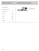
Assembly Tools Required

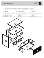
Part Identification

Hardware Identification

Assembly Steps

Français

Español

Safety

Warranty

No. 2 Phillips Screwdriver

Tip Shown Actual Size

3

4

5-24

25-28

29-32

33-34

35

Page 2

Summary of Contents for 5426510

Page 1: ...Hampstead Park Lateral Filer Model 5426510 Congratulations You are now an adult Teknik www teknikoffice co uk ...

Page 2: ... Contents Assembly Tools Required Part Identification Hardware Identification Assembly Steps Français Español Safety Warranty No 2 Phillips Screwdriver Tip Shown Actual Size 3 4 5 24 25 28 29 32 33 34 35 Page 2 ...

Page 3: ...e this part identification to help identify similar parts Now you know our ABCs A RIGHT END 1 B LEFT END 1 C FIXED SHELF 1 D ADJUSTABLE SHELF 1 D61 DRAWER BACK 1 D87 RIGHT DRAWER SIDE 1 D88 LEFT DRAWER SIDE 1 D729 DRAWER BOTTOM 1 E SKIRT 1 F DUST RAIL 1 G LOWER BACK 1 H UPPER BACK 1 J DRAWER FRONT 1 K TOP 1 M63 DRAWER BRACE 1 A B C D E F G H J K D61 D87 D88 D729 M63 Page 3 ...

Page 4: ...AIL 2 40MA 10A SLIDE CAM 2 FILE GLIDE 2 5B FILE ROD 2 9B FILE BRACKET 2 12B HIDDEN CAM 13 1F PULL 2 189K METAL BRACKET 5 4G WOOD DOWEL 10 15F CAM DOWEL 13 2F METAL PIN 4 1R RUBBER SLEEVE 4 2R CAM COVER 4 13P BLACK 9 16 LARGE HEAD SCREW 14 1S 3S GOLD 5 16 FLAT HEAD SCREW 4 BROWN 7 16 LARGE HEAD SCREW 4 6S 30S BLACK 1 9 16 FLAT HEAD SCREW 5 SILVER 1 2 FLAT HEAD SCREW 4 128S Page 4 ...

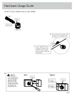
Page 5: ...n the HIDDEN CAM must point toward the hole in the edge of the board Hole Arrow Metal end Hidden Cam Cam Dowel Start Tighten Arrow Minimum 190 degrees Caution Risk of damage or injury HIDDEN CAMS must be completely tightened HIDDEN CAMS that are not completely tightened may loosen and parts may separate To completely tighten Arrow Maximum 210 degrees 3 Page 5 ...

Page 6: ... CAM DOWEL 2F into each HIDDEN CAM A Do not tighten the HIDDEN CAMS in this step 1F 2F Arrow Metal end Meet Part A This component has been engineered to be lighter stronger faster well ok Not technically faster But definitely makes for a sturdier lateral file that s easier to assemble and friendlier to the environment Page 6 Just think The sooner you do this the sooner you do something else ...

Page 7: ...NOTE For each EXTENSION RAIL turn a SCREW into the hole shown in the enlarged diagram Then slide the inner cartridge of the EXTENSION RAIL in to find the other hole that lines up with the hole in the RIGHT END Turn a SCREW into this hole å NOTE The EXTENSION SLIDES will be used later for the DRAWERS Step 2 A Open end Push the black lever in and pull the SLIDE from the RAIL 40MA 40MC 1 2 3 4 SILVER...

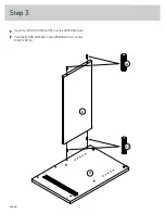
Page 8: ...å Insert four WOOD DOWELS 15F into the UPPER BACK H å Push the WOOD DOWELS in the UPPER BACK H into the RIGHT END A Step 3 A H 15F Page 8 15F ...

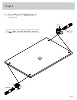
Page 9: ...our HIDDEN CAMS 1F into the FIXED SHELF C Then insert the metal end of a CAM DOWEL 2F into each HIDDEN CAM Step 4 C Do not tighten the HIDDEN CAMS in this step 1F 2F Arrow Metal end 1F 2F Metal end Arrow Page 9 ...

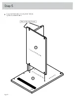
Page 10: ...å Fasten the FIXED SHELF C to the RIGHT END A Tighten two HIDDEN CAMS Step 5 A C Surface with HIDDEN CAMS Surface with HIDDEN CAMS Page 10 These surfaces should be even ...

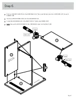
Page 11: ...ch HIDDEN CAM å Insert two WOOD DOWELS 15F into the LOWER BACK G å Fasten the LOWER BACK G to the RIGHT END A Tighten one HIDDEN CAM å NOTE Be sure the WOOD DOWELS in the LOWER BACK insert into the RIGHT END Step 6 A G G Arrow 1F 2F Metal end Arrow 1F 2F Metal end Surface with HIDDEN CAMS 15F Page 11 ...

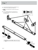
Page 12: ... are even with the edges of the SKIRT å Push two HIDDEN CAMS 1F into the DUST RAIL F Then insert the metal end of a CAM DOWEL 2F into each HIDDEN CAM Step 7 E F BLACK 9 16 LARGE HEAD SCREW 5 used in this step 1S Do not tighten the HIDDEN CAMS in this step Arrow 1F 2F Metal end Arrow 1F 2F Metal end Page 12 4G 4G 4G ...

Page 13: ... the SKIRT E Use three BLACK 9 16 LARGE HEAD SCREWS 1S through the METAL BRACKETS on the SKIRT and into the holes in the DUST RAIL Step 8 E F BLACK 9 16 LARGE HEAD SCREW 3 used in this step 1S Page 13 Surface with HIDDEN CAMS ...

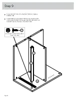
Page 14: ...A Tighten a HIDDEN CAM å Fasten SKIRT K to the RIGHT END A Use a BLACK 9 16 LARGE HEAD SCREW 1S through the METAL BRACKETS on the SKIRT and into the holes in the RIGHT END Step 9 E F A BLACK 9 16 LARGE HEAD SCREW 1 used in this step 1S Page 14 ...

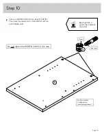
Page 15: ...Then insert the metal end of a CAM DOWEL 2F into each HIDDEN CAM Step 10 B Do not tighten the HIDDEN CAMS in this step 1F 2F Arrow Metal end Part B Another sturdier easier friendlier component Page 15 Now might be a good time to refresh your drink ...

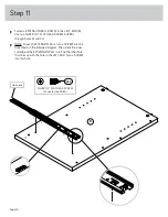
Page 16: ... For each EXTENSION RAIL turn a SCREW into the hole shown in the enlarged diagram Then slide the inner cartridge of the EXTENSION RAIL in to find the other hole that lines up with the hole in the LEFT END Turn a SCREW into this hole Step 11 Open end 3 2 1 4 B SILVER 1 2 FLAT HEAD SCREW 2 used for the RAILS 128S Page 16 ...

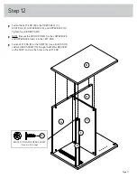
Page 17: ...å NOTE Be sure the WOOD DOWELS in the LOWER BACK and UPPER BACK insert into the LEFT END å Fasten LEFT END B to the SKIRT E Use a BLACK 9 16 LARGE HEAD SCREW 1S through the METAL BRACKET on the SKIRT and into the holes in the LEFT END Step 12 B H G C F E BLACK 9 16 LARGE HEAD SCREW 1 used in this step 1S Page 17 ...

Page 18: ...o the TOP K å Fasten the TOP K to the ENDS A and B Tighten four HIDDEN CAMS å NOTE Be sure the WOOD DOWELS in the TOP insert into the ENDS Step 13 A B K 15F 15F Part K Another sturdier easier friendlier component Page 18 Pro Tip Lift with your legs And you know your arms ...

Page 19: ...88 and DRAWER BRACE M63 Use five BLACK 1 9 16 FLAT HEAD SCREWS 30S Surface with HIDDEN CAM 1 2 3 4 Be sure the DRAWER BOTTOM inserts into the DRAWER FRONT groove Groove J J J D87 D88 Unfinished surface Be sure the DRAWER BOTTOM inserts into the DRAWER BACK groove 30S Start each screw a few turns before completely tightening any of them BLACK 1 9 16 FLAT HEAD SCREW 5 used in this step The tabs shou...

Page 20: ...Fasten the FILE BRACKETS 12B to the DRAWER BACK D61 and DRAWER FRONT J as shown Use four BROWN 7 16 LARGE HEAD SCREWS 6S Step 15 J D61 BROWN 7 16 LARGE HEAD SCREW 4 used in this step 6S 6S Page 20 12B 12B ...

Page 21: ...sible through the slotted hole in the SLIDE å Fasten the PULLS 189K to the DRAWER FRONT J as shown Use four BLACK 9 16 LARGE HEAD SCREWS 1S Step 16 Open end 10A Open end GOLD 5 16 FLAT HEAD SCREW 4 used for the SLIDES 3S Drawer Slide Center the screw in the oval hole 1 2 3 4 1 2 3 4 Screw head turn CAM to line up holes in the SLIDES with holes in DRAWER SIDES 10A J BLACK 9 16 LARGE HEAD SCREW 4 us...

Page 22: ... 9B through the FILE BARS 1B FILE BRACKETS and into the holes shown in the FILE GLIDE 5B on the RIGHT DRAWER SIDE D87 å Slide another FILE GLIDE 5B onto the other ends of the FILE RODS 9B then press this FILE GLIDE over the LEFT DRAWER SIDE D88 Step 17 5B D88 D87 Use the exact holes shown 1B 1B 9B 9B 5B Use the exact holes shown 12B 12B Page 22 ...

Page 23: ...and B Set the ADJUSTABLE SHELF D onto the METAL PINS å To insert a drawer into your unit line up the EXTENSION SLIDES on the drawer with the EXTENSION RAILS on the unit and push the drawer into the unit until the drawer is fully inserted The drawer will push in hard until it is all the way in then it will slide in and out easier Step 18 4 used 1R 2R B A D 35 lbs 25 lbs 25 lbs 35 lbs Page 23 13P 4 ...

Page 24: ...REWS when finished with adjustments å NOTE Please read the back pages of the instruction booklet for important safety information å This completes assembly Clean with a damp cloth Wipe dry Step 19 Cam The higher the screw in the oblong hole the higher your drawer front will be The lower the screw the lower the drawer front Loosen screw 4 a 1 4 turn turn the cam a 1 4 turn maximum in both the clock...

Page 25: ...lace the heavier items in the lower drawer Improperly moving furniture Furniture can tip over or break if improperly moved Physical injury Furniture can be very heavy Unload drawers from top to bottom before moving the lateral file Do not push furniture especially on a carpeted floor Have a friend help you lift the item and set it in place Placing TVs on furniture items that are not designed to su...

Reviews: