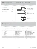


Table of Contents
Assembly Tools Required
3
4
5-22
31
Part Identifi cation
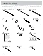
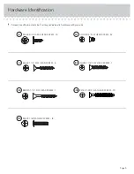
Hardware Identifi cation
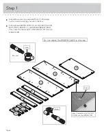
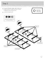
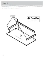
Assembly Steps
418706
www.sauder.com/services
Page 2
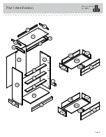
Part Identifi cation
å
While not all parts are labeled, some of the parts will have a label or an inked letter on the edge
to help distinguish similar parts from each other. Use this part identifi cation to help identify similar parts.
A
RIGHT END (1)
B
LEFT END (1)
C
TOP (1)
D
BOTTOM (1)
E
BACK (1)
F
BRACE (3)
G
BASE (1)
I
RIGHT BASE (1)
J
LEFT BASE (1)
K
UPPER DRAWER FRONT (1)
L
DRAWER FRONT (3)
M
FRONT MOLDING (1)
N
RIGHT MOLDING (1)
O
LEFT MOLDING (1)
P
BACK RAIL (1)
R
SIDE RAIL (2)
D22
DRAWER RIGHT SIDE (3)
D23
DRAWER LEFT SIDE (3)
D26
SMALL DRAWER RIGHT SIDE (1)
D27
SMALL DRAWER LEFT SIDE (1)
D182
SMALL DRAWER BACK (1)
D183
DRAWER BACK (3)
D987 DRAWER BOTTOM (4)
M64
DRAWER BRACE (4)
Hammer
Not actual size
No. 2 Phillips Screwdriver
Tip Shown Actual Size
Skip the power trip.
This time.