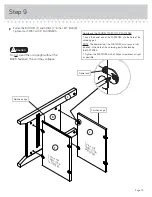
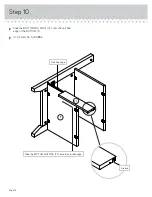
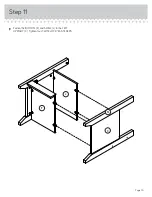
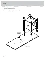

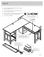
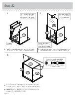


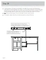
Step 23
Page 27
å
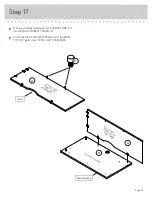
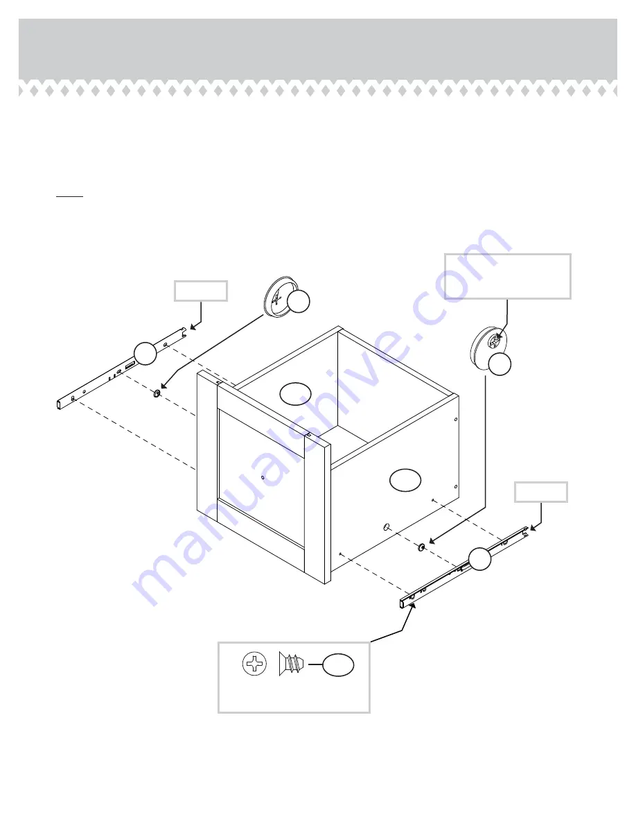
Insert a SLIDE CAM (YY) into the DRAWER SIDES (D14 and D15).
å
Fasten the EXTENSION SLIDES (KK) to the DRAWER
SIDES (D14 and D15). Use four GOLD 5/16" FLAT HEAD
SCREWS (FFF) through holes #1 and #3.
å
NOTE: The screw head in the CAM must be visible through the
slotted hole in the SLIDE.
Screw head - turn CAM to
line up holes in SLIDES with
holes in DRAWER SIDES.
KK
KK
YY
YY
1
2
3
1
2
3
Open end
Open end
D15
D14
GOLD 5/16" FLAT HEAD SCREW
(4 used in this step)
FFF