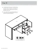

Step 16
å
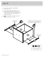
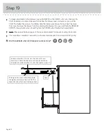
Insert a SLIDE CAM (RR) into each DRAWER
SIDE (D28 and D29).
å
Fasten the LONG RIGHT DRAWER SLIDE (V) to the
RIGHT DRAWER SIDE (D28) and the LONG LEFT
DRAWER SLIDE (W) to the LEFT DRAWER SIDE (D29).
Use four GOLD 5/16" FLAT HEAD SCREWS (CCC)
through holes #1 and #3.
å
NOTE: The screw head in the CAM must be visible
through the slotted hole in the SLIDE.
www.sauder.com/services
Screw head - turn CAM to line up holes in
the SLIDES with holes in DRAWER SIDES
RR
RR
V
W
Roller end
Roller end
GOLD 5/16" FLAT HEAD SCREW
(4 used in this step)
CCC
1
2
3
1
2
3
D28
D29