Copyright © D 031 - 06/00
2 of 4
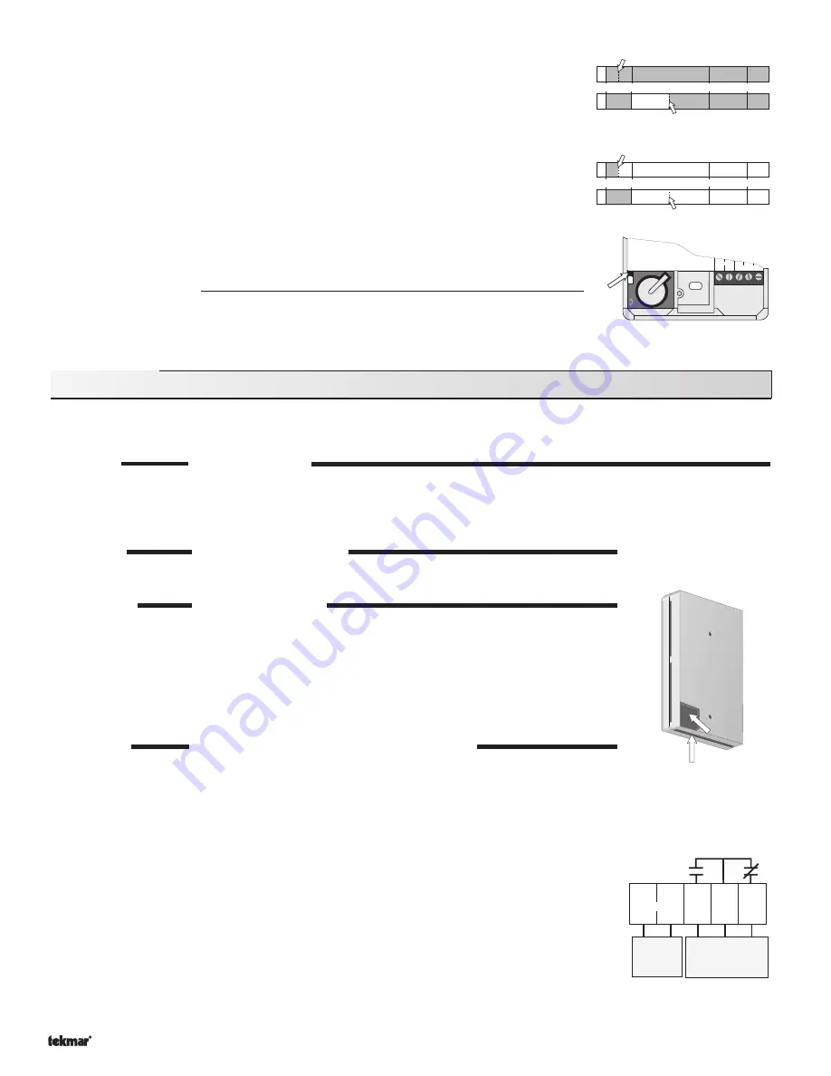
Permanent Occupied Override
When the Timer 031 is in Occupied mode and a Permanent Occupied Override is selected, the
OVR element is displayed and the Timer remains in Occupied mode until the Override is
cancelled.
When the Timer is in UnOccupied mode and a Permanent Occupied Override is selected, the
OVR
element is displayed and the Timer switches to Occupied mode until the Override is cancelled.
Note:
The OVR element turns off when the Permanent Override is cancelled.
Permanent UnOccupied Override
When the Timer is in Occupied mode and a Permanent UnOccupied Override is selected, the
OVR element is displayed and the Timer switches to UnOccupied mode until the Override is
cancelled.
When the Timer is in UnOccupied mode and a Permanent UnOccupied Override is selected,
the
OVR element is displayed and the Timer remains in the UnOccupied mode until the Override
is cancelled.
Note:
The OVR element turns off when the Permanent Override is cancelled.
Optimum Start / Stop
The Timer 031 has an
Optimum Start / Stop option which synchronizes the Timer 031 UnOccupied
schedule with the
Optimum Start / Stop feature on tekmar controls. The Timer 031 also
communicates the Override options to tekmar controls. The
Optimum Start / Stop feature is
enabled by switching the DIP switch in the wiring chamber to the
On position.
Installation
Caution
Improper installation and operation of this control could result in damage to equipment and possibly even personal injury. It
is your responsibility to ensure that this control is safely installed according to all applicable codes and standards.
STEP ONE
GETTING READY
Check the contents of this package. If any of the contents listed are missing or damaged, please contact your wholesaler or tekmar sales
representative for assistance.
Type 031 includes
• One Timer 031
• One Data Brochure D 031 and one Data Brochure D 001
STEP TWO
MOUNTING THE BASE
The Timer 031 is mounted in accordance with the instructions given in the Data Brochure D 001 for
Enclosure C.
STEP THREE
ROUGH-IN WIRING
All electrical wiring terminates in the wiring chamber at the bottom of the Timer 031. The wiring to the Timer
031 is either inserted through the gap in the bottom of the enclosure or through the hole provided in the back
of the enclosure.
Power should not be applied to any of the wires during the rough-in wiring stage.
Run 18 AWG or similar wire from either a 24 V (ac) power supply or a 32 V (dc) power source to the wiring
chamber in the Timer 031. Do not connect the wires to any terminal until the voltage has been properly
tested.
Run 18 AWG or similar wire from the control to the wiring chamber in the Timer 031.
STEP FOUR
TESTING AND CONNECTING THE WIRING
A good quality electrical test meter, capable of measuring 0 to 200 Volts is essential to properly test the
Timer 031.
Ensure exposed wires are not grounded or in contact with other wires and turn on the power supply. If a
24 V (ac) transformer is used, make sure the voltmeter is set to AC. With the voltmeter leads connected
to the secondary side of the transformer, you should measure between 22 and 26 V (ac). If a 32 V (dc) power
source is used, make sure the voltmeter is set to DC. Connect the positive lead from the voltmeter to the
positive terminal on the DC source and the negative lead from the voltmeter to the negative terminal on the
DC source. The voltmeter should measure between 26 and 38 V (dc). Turn the power off.
Connect the 24 V (ac) power supply to the
C- — R+ (1 and 2) terminals on the 031. If a 32 V (dc) power
source is used, the negative lead (-) of the source should be connected to the
C- (1) terminal and the positive
lead (+) to the
R+ (2) terminal. When a (dc) power supply is used or if the (ac) power supply does not operate
at a stable frequency of 60 Hz, the jumper located in the wiring chamber of the 031 must be cut.
When the Timer 031 is used with a tekmar control, connect one end of the 18 AWG or similar wires to the
N/O — Com (3 and 4) terminals on the 031 and connect the other end to the Com Sen — UnO Sw terminals
on the tekmar Control. For more information about wiring to the control, consult the Data Brochure supplied
with the control.
Note:
The Com — N/C (4 and 5) terminals can be used to provide a closed contact during the
Occ event and an open circuit during the UnOccupied event.
24 V (ac) or
32 V (dc)
power
supply
To: Unoccupied Input
N/O closes during UnOcc
N/C opens during UnOcc
1
C-
2
R+
3
4
5
N/0
Com N/C
Power
Wiring can enter through
the back or the bottom of
the enclosure.
6 AM 9 AM
5 PM
10 PM
Permanent Occupied
Override at 1 PM
Permanent Occupied
Override at 7:30 AM
6 AM 9 AM
5 PM
10 PM
Permanent UnOccupied
Override at 1 PM
Permanent UnOccupied
Override at 7:30 AM
Power
Relay contacts
N/O Com
C
R
Lithium CR1620
POS (+) up
Cut jumper
for non-60Hz
Of
f | On
—
Opti
DIP
switch


