background image


7.1. Reset to maintenance state


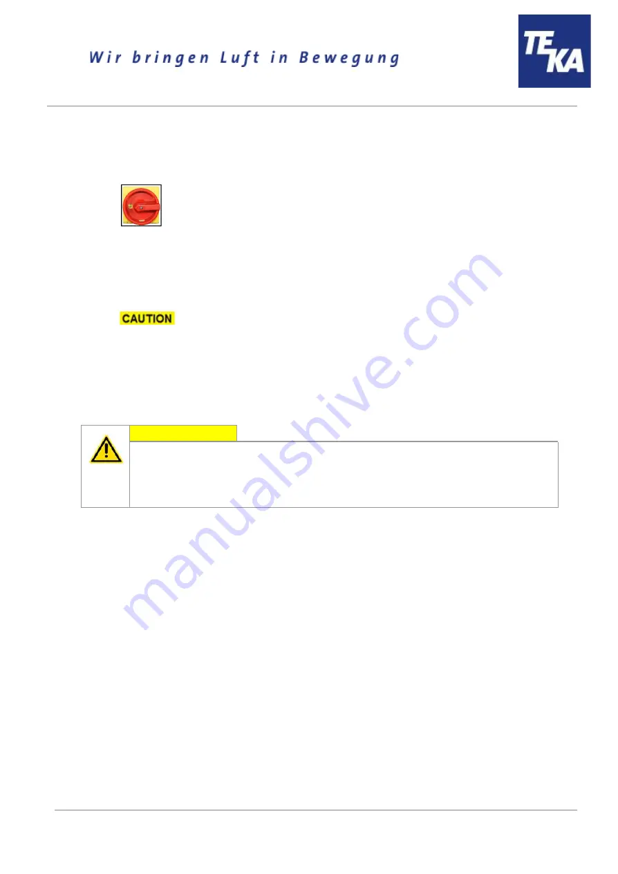
Switch off the unit. Then disconnect the unit from the power supply by setting the main switch in


the “OFF” position. Secure the unit against unauthorized restarting during maintenance. 


Disconnect the compressed air hose of the external compressed air supply from the insert


sleeve (see chapter 2.1). 

Empty the compressed air tank by opening the drain valve (see chapter 2.1) with a suitable


screwdriver. Minor quantities of condensation water can leak out when opening the drain valve.


Close the drain valve when the compressed air tank is entirely empty. 

 When opening the drain valve a compressed air blast can occur! 

After completion of all maintenance work the unit can be reconnected to the power supply and


the external compressed air supply. 


7.2. Cleaning the filter cartridges 


CAUTION 


A sudden jet of compressed air and huge amounts of whirled up dust are possible


due to an automatic cleaning with an opened service door. 

During the operation of the device, the service door of the filter housing must not be opened.


The same applies to the ready to operate condition (standby) as there is also the possibility


of an automatic cleaning (subsequent cleaning). 

 
The filter cartridges are reusable filters and can be cleaned. The cleaning of the filter cartridges is


automatically carried out. 

The degree of pollution of the filter cartridges is electronically monitored. In order to assure the required


extraction capacity of the device, the cleaning of the filter cartridges starts automatically when a preset


differential pressure value is reached. If the preset differential pressure value is not undercut after the


cleaning of the filter cartridges, another cleaning starts. The filter unit remains in operation during the


automatic cleaning. The compressed air blast is produced in opposite direction to the intake. The


cleaned dust falls downwards in the dust collecting tank. 
Depending on the setting of the control unit there can be automatic postcleanings of the filter cartridges


even when the unit is switched off. 

When the maximal admissible differential pressure value is reached, the device triggers an alarm (see


chapter “description of the control elements”). If despite of the automatic cleaning of the filter cartridge


the alarm value is not undercut anymore, the filter cartridge must be replaced. (see chapter: “Replacing


the filter cartridges”). 
The differential pressure values in the control unit that initiate a cleaning or a filter alarm are preset


values adapted to the filter unit. Please find detailed information concerning the functioning in the


enclosed operating instructions of the control unit. 


BA_Airtech_P10_IFA_190319_EN 

14 

19.03.2019 


Summary of Contents for Airtech P10

Page 1: ...ng instructions Translation of the original operating instructions Airtech P10 TEKA Absaug und Entsorgungstechnologie GmbH Industriestraße 13 D 46342 Velen Tel 49 2863 9282 0 E Mail info teka eu www teka eu 1 ...

Page 2: ...Precoating of the filter cartridges 11 5 3 Connecting the compressed air supply 11 5 3 1 Compressed air supply for the cleaning of the filter cartridges 11 6 Operating the system 12 6 1 Explanation of the operating elements 12 7 Maintenance 13 7 1 Reset to maintenance state 14 7 2 Cleaning the filter cartridges 14 7 3 Replacing the filter cartridges 15 7 4 Emptying the dust collecting tank 17 7 5 ...

Page 3: ... observe the following for a successful use of the device Only authorised and instructed personnel can carry out transport operation maintenance and repair of the device The operator must ensure that the operating personnel take note of these instructions Please read these instructions before operating the device and observe the safety precautions to avoid injury Store this manual in a safe place ...

Page 4: ...Pos 6 Dust collecting housing Filter housing Cleaning housing Fan housing Air outlet plenum Ejection nozzles Pos 7 Pos 8 Pos 9 Pos 10 Pos 11 Intake ducts intake elements as an option Forklift skids Connection for compressed air Drain valve for compressed air Connection for C tube BA_Airtech_P10_IFA_190319_EN 4 19 03 2019 ...

Page 5: ...loyed steels as well as of high alloy chromium nickel steels and therefore meets the highest welding fume separation category W3 according to DIN EN ISO 15012 1 WARNING Improper use can damage parts and be a danger to life and limb The device must not be used for the extraction of oil laden welding fume explosive dust and gases hybrid mixtures glowing or burning substances gases water etc The devi...

Page 6: ... carried out by authorised and qualified personnel We therefore recommend using the training protocol on the last page for that purpose see chapter Training protocol Laymen are allowed to operate the device after having received the necessary instructions But they are not allowed to carry out any installation repair or maintenance work Dangers arising from fire In case of fire if possible switch t...

Page 7: ...ating load Lift trucks forklift trucks and transport cranes must have a sufficient minimum load bearing capacity Dangers arising from titling or functional impairments at its destination The unit may only be set up on a suitable surface The unit may only be set up on a suitable surface The surface must be vibration free and horizontal The operator must check the bearing capacity of the surface The...

Page 8: ...nit onto this part with the help of the screws included in the delivery You can lift it with the help of the forklift skids D located at the connection cover Adjust the ejection nozzles E Fix the intake ducts F to the extraction housing with the help of the assembly material included in the delivery The holes of the grid must be adjusted to the front As an option intake elements can be used additi...

Page 9: ...attached before turning the unit on Do not operate the unit if any components are defective missing or damaged Check the orderly condition of the unit before switching it on The unit must not be operated without a filter element NOTICE Damaged supply lines Make sure that the supply lines are protected against damage by forklift trucks and similar events Protect all supply lines from heat moisture ...

Page 10: ...ecifications on the type plate Mount the housing of the external control if it is not mounted on the device itself close to the device on the wall or at any other appropriate mounting point Or mount the control together with a cabinet console on a suitable surface for example using lag bolts or heavy duty anchors The housing is not suited for outdoor installation Connect all visible cables and hos...

Page 11: ...m are automatically cleaned Cleaning is carried out pneumatically via a built in compressed air tank Without compressed air supply the filter cartridges will become dirty very quickly The external compressed air supply must be assured with an approved compressed air hose For the connection to the device the compressed air hose must be equipped with a quick coupling for an insert sleeve DN 7 2 The ...

Page 12: ...ate The main switch also serves as an emergency off switch Emergency stop button This button can be used to switch off the unit in an emergency When switched off the unit is not de energised The unit cannot be switched on again until the button has been unlocked Operating elements for status and error messages Representa tion Designation Description function Stroboscope flash The stroboscope flash...

Page 13: ...fe and limb When cleaning and servicing equipment during the replacement of parts or when changing to another function set the device to maintenance condition first see chapter Reset to maintenance state A recommissioning of the device must only occur if it is ensured that the device is functionally equivalent to the original state CAUTION Hazards to the respiratory tracts are possible All mainten...

Page 14: ... cleaned The cleaning of the filter cartridges is automatically carried out The degree of pollution of the filter cartridges is electronically monitored In order to assure the required extraction capacity of the device the cleaning of the filter cartridges starts automatically when a preset differential pressure value is reached If the preset differential pressure value is not undercut after the c...

Page 15: ...om the power supply After the cleaning disconnect the filter unit from the power supply and secure it against being switched on again After cleaning the filter cartridges wait about 5 minutes before opening the service door of the filter housing We recommend to pretreat new filter cartridges with filter aid e g precoat before the first commissioning Refer to the chapter Precoating new filter cartr...

Page 16: ... generating dust Take the displacer pos D out of the filter cartridge without generating dust Carefully close the disposal bag e g with a cable fastener and store or dispose of it together with the polluted filter cartridge in an appropriate container according to the regulations Insert the displacer into the new filter cartridge in a way that the screw of the displacer is put through the hole of ...

Page 17: ...fore emptying the dust collecting tank hold ready an appropriate container e g PE bag The bags are optionally available at TEKA see list of spare parts We recommend having PE bags in stock Open the service door of the dust collecting housing see chapter 2 1 Open the toggle levers B of the dust collecting tank A Risk of contusion when opening the toggle levers Carefully pull the dust collecting tan...

Page 18: ...ds heavily on the quality of the compressed air and cannot therefore be determined in advance CAUTION When opening the drain valve a blast of compressed air is possible Open the drain valve slowly Empty the compressed air tank by opening the drain valve see chapter 2 1 with a suitable screwdriver Let the escaping condensate flow into a suitable container Close the drain valve BA_Airtech_P10_IFA_19...

Page 19: ...on level Hand protection Protective gloves in cloth rubber or leather Eye protection Safety glasses with side shields Body protection Anti static work shoes CAUTION During operation of the device an automatic cleaning can take place This involves the risk of a sudden jet of high pressure air and excessive dust formation at the point of entry of the filter aid At first make sure that there is no co...

Page 20: ...losed operating manual of the control unit Faults indicated by control elements are explained in the chapter Description of the control elements A recommissioning of the device must only occur if it is ensured that the system is functionally equivalent to the original state Repairs may only be carried out by TEKA personnel or after consultation with TEKA GmbH by the personnel authorised by the ope...

Page 21: ...high Reduce the compressed air Escape of dust at the hinge The hinge must be reoriented or replaced Suction power too low smoke hardly extracted Filter element is saturated Replace the filter package dispose of old filter properly Filter elements are saturated because no compressed air is connected Connect compressed air The motor rotates in the wrong direction The rotating field of mains connecti...

Page 22: ... x 1200 mm 4 pieces of these filter elements are required for the device 1000501420250 Disposal elements Article no PE bag for the disposal of filter cartridges 4 pieces 10030251702 PE bag for inserting into the dust collecting tank 10 pieces 10030251 Precoat consumable Article no Precoat for filter cartridges 400g im Eimer 951004 Precoat für filter cartridges 100g im Eimer 9510050001 BA_Airtech_P...

Page 23: ...g to EN ISO 15012 1 W3 Width without with intake ducts Depth Height mm mm mm 800 4900 1200 4000 Weight without with intake ducts kg ca 700 900 Sound pressure level measured according to DIN 45635 1 dB A ca 72 Allowed ambient temperature C 5 to 35 Allowed max humidity 70 Compressed air supply dry oil free Necessary external pressure bar see chapter Connecting the compressed air supply BA_Airtech_P1...

Page 24: ...e from the serial number A16800010011001 resp P36000010011001 on conforms to the following directives Machinery Directive 2006 42 EG Electromagnetic Compatibility 2014 30 EU Pressure equipment directive 2014 68 EU This declaration will become void if the device is exposed to modifications that are not approved by the manufacturer in written form Authorized representative for the technical document...

Page 25: ...has been instructed regarding the following items Instruction completed Description of the device Operation and application of the device Explanation of the safety instructions Behavior in case of fire Explanation of the operation elements Change and dedusting of the filter elements Emptying of the dust collecting tank Appropriate disposal Maintenance works Maintenance intervals Name of the employ...

Page 26: ...by the filter unit and thus is not subject to a maintenance interval The filter unit triggers an alarm when a replacement of the filter cartridges is necessary Emptying the dust collecting tank or check of fill level 7 4 weekly Draining the condensate 7 5 monthly 14 2 General maintenance The described maintenances are independent from the demands of the system operations The operator is obliged to...

Page 27: ...nning cables for damages Check the dust collecting tank for tightness check the sealing rubber of the tank 14 2 2 Visual inspection of the pipelines for dust deposits Visual inspection Observation that there are no visible safety related defects WARNING Danger arising from the ready to operate condition of the device Follow the procedure as described in the chapter Set to maintenance state The fol...

Page 28: ...dust is escaping from the unit during the dedusting cycle A functional test should always be carried out with a connected producing machine tool Check if the collection of the fume or dust is sufficient Visual inspection 14 2 5 Electrical test of the electrical lines and earthing connections WARNING Danger arising from electricity The operator is responsible for ensuring that all work on electric ...

Reviews: