background image

9. Diagnostics and troubleshooting

A list of possible system errors is provided in the table.

Faults indicated by control elements are explained in the chapter “Description of the control
elements”.

A recommissioning of the device must only occur if it is ensured that the system is functionally
equivalent to the original state. Repairs may only be carried out by TEKA personnel or, after
consultation with TEKA GmbH, by the personnel authorised by the operator.

Adhere to the instructions in the chapter "Safety instructions" and " Maintenance" when carrying out any
repairs. If in doubt, contact our TEKA service department:

Tel:

+49 2541-84841-0

E-mail: [email protected]

Fault

Cause

Removal

System does not start.

Plug power supply is missing or
incorrectly inserted.

Plug connector check power
supply / plug in correctly.

No power at outlet.

Check the mains, remove error if
possible.

Suction power too low

Filter element is saturated.

Replace the filter package,
dispose of old filter properly!

Suction line contracted.

Check and fix.

Exhaust line contracted.

Check and fix.

10. List of spare parts

Filter element

Article no.

Gross filter  (10 pieces)

978003

Prefilter

978004

Particle filter

“H14”

978005141

Activated carbon filter

978006

Disposal elements

Article no.

PE-bag for the disposal of filter elements (3 pieces)

10030257

BA_VIROLINE-COMPAC_210831_EN

13

12.01.2022

Summary of Contents for 21110800

Page 1: ...g instructions Translation of the original operating instructions VIROLINE COMPAC TEKA Absaug und Entsorgungstechnologie GmbH Millenkamp 9 D 48653 Coesfeld Tel 49 2541 84841 0 E Mail info teka eu www teka eu 1 ...

Page 2: ...7 5 2 Assembling the silencing housing option 8 5 3 Locking the maintenance door 8 5 4 Electrical connection 9 6 Operating the system 9 6 1 Explanation of the operating elements 9 7 Maintenance 10 7 1 Reset to maintenance state 11 7 2 Replacing the filter elements 11 8 Dismantling Disposal 12 9 Diagnostics and troubleshooting 13 10 List of spare parts 13 11 Technical data 14 12 EC declaration of c...

Page 3: ...air of the device The operator must ensure that the operating personnel take note of these instructions Please read these instructions before operating the device and observe the safety precautions to avoid injury Store this manual in a safe place These instructions are to be regarded as a component of the product Adhere to all product notes Modifications or conversions that the operator carries o...

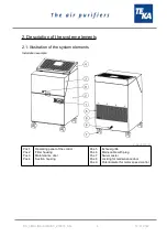
Page 4: ...r 20513701 Pos 1 Pos 2 Pos 3 Pos 4 Operating panel of the control Filter housing Maintenance door Suction housing Pos 5 Pos 6 Pos 7 Pos 8 Pos 9 Exhaust grille Mains cable with plug Swivel castor Locking for maintenance door Potentiometer for motor speed control BA_VIROLINE COMPAC_210831_EN 4 12 01 2022 ...

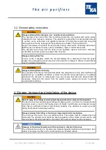
Page 5: ...mage parts and be a danger to life and limb The device must not be used for the extraction of oil laden welding fume explosive dust and gases hybrid mixtures glowing or burning substances gases water etc The device must not be operated in explosive zones 3 Safety instructions 3 1 Definition of the hazard symbols The device is constructed according to the state of the art and the recognised safety ...

Page 6: ...ified electrician or under the direction and supervision of a qualified electrician Do not work on components if you are not sure that these are disconnected If necessary disconnect the device from the electric power supply and secure it against unauthorized restarting 4 Storage transport and installation of the device WARNING Risk of injury from tilting or unmounted components when stored or tran...

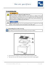
Page 7: ...n of the unit before switching it on The unit must not be operated without a filter element NOTICE Damaged supply lines Make sure that the supply lines are protected against damage by forklift trucks and similar events Protect all supply lines from heat moisture oil and sharp edges 5 1 Assembling the suction housing This chapter is only relevant if the suction housing has not yet been installed Mo...

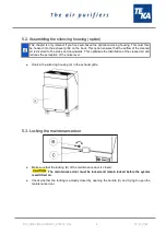
Page 8: ...This optimizes the distribution of the cleaned air and reduces the perception of the noise level Hook in the silencing housing A in the exhaust grille 5 3 Locking the maintenance door Make sure that the locking B of the maintenance door is closed The maintenance door must be locked and remain locked before the system is switched on Check whether the locking is actually closed by opening the handle...

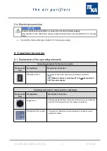
Page 9: ...resenta tion Designation Description function ON OFF switch By means of this switch the device is switched on and off When the device is switched off it is not disconnected from the power supply Operating elements for status and error messages Representa tion Designation Description function Signal horn Honking signals that the air flow rate of the device is not sufficient anymore Filter elements ...

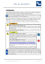
Page 10: ...al state CAUTION Hazards to the respiratory tracts are possible All maintenance work must only be carried out in well ventilated rooms and while wearing an appropriate respiratory mask We recommend respiratory protection half mask DIN EN 141 143 protection level P3 For all maintenance work ensure a cautious handling of filter elements and components in order to avoid whirling up dust Notes regardi...

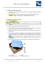
Page 11: ...ion Now grasp the wooden side at the back and lift the main filter carefully out of the device Place the main filter onto one of its wooden sides in order not to damage or pollute the sealing at the bottom Which filter element must be replaced depends on the pollution degree of the individual filters It can vary and depends on the application However please consider our recommended changing interv...

Page 12: ...e dismantling of the machine it has to be disconnected from the power supply and all supply lines CAUTION Whirling up dust is possible due to the deposited dust During all work a suitable respiratory protection and protective clothing have to be worn The operator is obliged to store and dispose of the collected dust in accordance with national or regional regulations BA_VIROLINE COMPAC_210831_EN 1...

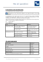
Page 13: ... in doubt contact our TEKA service department Tel 49 2541 84841 0 E mail info teka eu Fault Cause Removal System does not start Plug power supply is missing or incorrectly inserted Plug connector check power supply plug in correctly No power at outlet Check the mains remove error if possible Suction power too low Filter element is saturated Replace the filter package dispose of old filter properly...

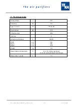
Page 14: ...power kW 0 55 Protection class IP54 ISO class F Extraction performance 99 995 Width Depth Height mm mm mm 580 580 1010 Weight kg 90 Allowed ambient temperature C 5 to 35 during operations 10 to 40 during transport and storage Allowed max humidity 70 BA_VIROLINE COMPAC_210831_EN 14 12 01 2022 ...

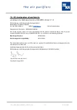
Page 15: ...ed above from the serial number A18200010011001 resp P39000010011001 on conforms to the following directives Machinery Directive 2006 42 EG Electromagnetic Compatibility 2014 30 EU This declaration will become void if the device is exposed to modifications that are not approved by the manufacturer in written form Authorized representative for the technical documentation TEKA Absaug und Entsorgungs...

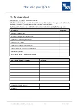
Page 16: ...yee confirms that he has been instructed regarding the following items Instruction completed Description of the device Operation and application of the device Explanation of the safety instructions Behavior in case of fire Explanation of the operation elements Change and dedusting of the filter elements Appropriate disposal Maintenance works Maintenance intervals Name of the employee legible Signa...

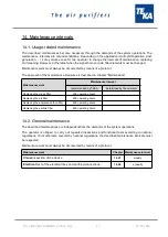
Page 17: ...KA determined by the operator Replacing the gross filter 300 operating hours Replacing the prefilter 600 operating hours Replacing the activated carbon filter 600 operating hours Replacing the particle filter 600 operating hours 14 2 General maintenance The described maintenances are independent from the demands of the system operations The operator is obliged to carry out repeated inspections and...

Page 18: ...ctrical test of the electrical lines and earthing connections WARNING Danger arising from electricity The operator is responsible for ensuring that all work on electric components is carried out by authorised and qualified personnel The device is subject to regular electrical checks by the operator of the device and are subject to national standards of the different countries The here recommended ...

Reviews: