Teikoku USA | Chempump
Instruction Manual NC-Series 0220
8
4. Provide for pipe expansion when required by liquid tempera-
ture.
5. When welding joints, avoid possibility of welding shot enter-
ing the suction or discharge line, and thereby entering the
pump.
Caution!
Do not weld pipe when it is connected to pump.
6. Do not spring piping when making up any connections.
7. Make suction piping as straight as possible, avoiding unneces-
sary elbows. Where necessary, use 45 degree or long-sweep
90 degree fittings.
8. Make suction piping short, direct, and never smaller in diam-
eter than suction opening of pump. Suction piping should
be equal to or larger than pump suction port, depending on
pipe length.
9. Ensure that all joints in suction piping are airtight.
10. When installing valves and other fittings, position them to
avoid formation of air pockets.
11. Permanently mounted suction filters are not recommended.
It is extremely important to size and layout the suction system to
minimize pressure losses and to be sure that the pump will not be
“starved” for fluid during operation. NPSH problems are a result
of improper suction systems.
If suction pipe length is short, pipe diameter can be the same size
as the pump suction port diameter. If suction piping is long, the
size should be one or two sizes larger than pump suction port,
depending on piping length.
Use the largest pipe size practical on suction piping and keep pip-
ing short and free from elbows, tees or other sources of pressure
drops. If elbows or tees must be used, locate them from 10 to 15
pipe diameters upstream from suction. When reducing to pump
suction port diameter, use eccentric reducers with eccentric side
down to avoid air pockets.
When operating under conditions where pump prime can be
lost during off cycles, a foot valve should be provided in the suc-
tion line to avoid the necessity of priming each time the pump is
started. This valve should be of the flapper type rather than the
multiple spring type and of ample size to avoid undue friction in
the suction line.
When foot valves are used, or when there are other possibilities of
fluid hammer, it is important to close the discharge valve before
shutting down the pump.
When necessary to connect two or more pumps to the same suc-
tion line, provide gate valves so that any pump can be isolated
from the line. Install gate valves with stems horizontal to avoid air
pockets. Globe valves should be avoided, particularly where NPSH
is critical. If discharge pipe length is normal, pipe diameter can be
the same size as the pump discharge port diameter. If discharge
piping is of considerable length, use larger diameter pipe (one or
two sizes larger).
If the pump is to discharge into a closed system or an elevated
tank, place a gate valve or check valve in the discharge line close
to the pump. The pump can then be opened for inspection with-
out fluid loss or damage to the immediate area.
NOTE:
Install properly sized pressure gauges in suction and dis-
charge lines between the pump and the first block and/or check
valve so that operation of the pump and system can be easily
observed. Should cavitation, vapor lock, or unstable operation oc-
cur, widely fluctuating discharge pressures will be observed. Such
gauges provide a positive means of determining actual system
conditions and can be used to great advantage in evaluating sys-
tem problems.
2.3 Electrical and Instrumentation
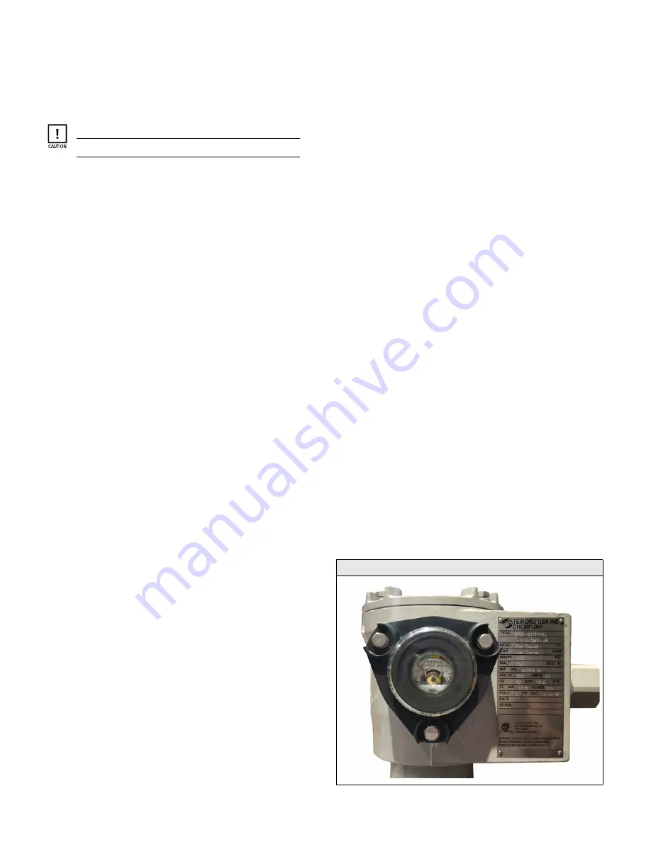
2.3.1 TRG Bearing Wear Monitor
The TRG is an electrical meter that continuously monitors the con-
dition of the bearings. The TRG is mounted on the electrical junc-
tion box as standard.
The TRG meter operates on the principle of induced voltage.
There are two TRG coils located inside the stator 180° apart. A
magnetic field is created in the stator by current flowing through
the stator windings. In addition, a magnetic field is created by
induced currents in the rotor. When the rotor is perfectly centered
in the stator, the two magnetic fields are essentially balanced.
When bearing wear occurs and the gap between the rotor and
stator decreases, an imbalance in the magnetic fields causes a dif-
ferential induced voltage in the TRG coils. This differential voltage
is indicated on the TRG voltmeter.
The initial display of the TRG meter is adjusted in the Teikoku
factory, but each meter will show subtle differences. To check
bearing wear using the TRG meter, use the color change (Green,
Yellow, Red) as a reference. If the increase of TRG readings is 0.3
or more, stop the pump and check bearings.
The Teikoku Rotary Guardian (TRG) signal is affected by motor
load. Changes in operating frequency or hydraulic load may in-
crease or decrease signal.
Keeping records of the TRG meter reading in conjunction with
motor amp readings will provide a good indication of when the
pump will require maintenance.
Figure 2-1. Teikoku TRG Bearing Wear Monitor


