RS-232 signals
D-Sub 9
DCD
1
RXD
2
TXD
3
DTR
4
GND (common ground)
5
DSR
6
RTS
7
CTS
8
RI
9
Table 3. RS-232 Connector Pinout.
RS-422 signals
RS-485 signals
D-Sub 9
GND (common ground)
1
RXD+ termination impedance
2
RXD- termination impedance
3
TXD+, or TXD/RXD+ termination impedance
4
TXD-, or TXD/RXD- termination impedance
5
RXD+ (B)
- - -
6
RXD- (A)
- - -
7
TXD+ (B)
TXD/RXD+ (B)
8
TXD- (A)
TXD/RXD- (A)
9
Table 4. RS-422/485 Connector Pinout.
Note:
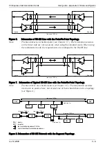
The circuit schematics including the termination resistors topology is shown in
Figure 4.
The user may activate the termination impedances by connecting the
corresponding pins at the D-Sub 9 connector (identical to all TEDIA PCI and ISA
communication cards) or by setting the appropriate jumper; see Figure 5.
PCI Express Communication Cards
User guide - Appendix II, Tables and Figures
rev. 10.2009
II - 4
Summary of Contents for PCI-1482E
Page 1: ...PCI Express Communication Cards User Guide...
Page 18: ...PCI Express Communication Cards User Guide Notes...
Page 19: ......


