background image

                      AG-300 Plus Gateway User Manual


11. 

Installation Reference


11-1 Vertical


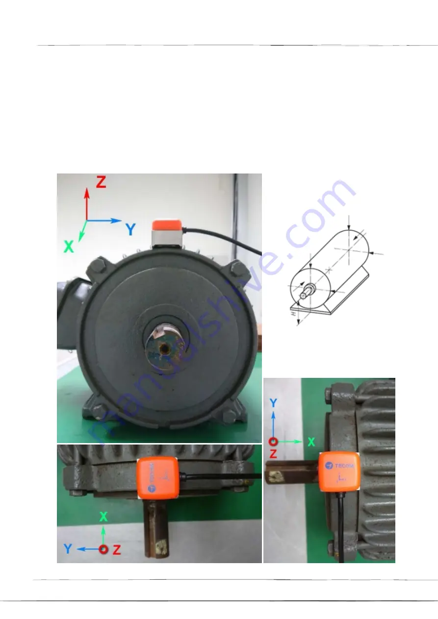
When the vibration  gauge is installed in the vertical direction, it should be placed just above 

the  rotating shaft. At this time, the Z-axis of the vibration gauge is the vertical direction. 

Please note that the two  legs of the magnet are parallel to the rotating shaft so that they can 

be fixed on the arc surface of the motor on.


Z


Y


X


Z


Y


X


X


Z


X


Y


X


X


Z


X


Y


X


When using the vertical installation 

position, the figure represents the 

measured correct X, Y, Z vibration axis.


Page


16


Summary of Contents for AG-300 Plus

Page 1: ...AG 300 Plus Gateway User Manual Copyright 2018 All Rights Reserved Ver R02 D C 106 1123 ...

Page 2: ...nterference that may cause undesired operation CE Declaration of Conformity This equipment complies with the requirements relating to electromagnetic compatibility EN55032 class B for ITE and EN 50082 1 This meets the essential protection requirements of the European Council Directive 89 336 EEC on the approximation of the laws of the Member States relating to electromagnetic compatibility Environ...

Page 3: ...nvironment This could cause unexpected issues 10 Do not work on the system or connect or disconnect cables during lightning storms 11 Children do not recognize the risks of electrical appliances Therefore use or keep the device only under supervision of adults or out of the reach from children 12 No repair can be performed by the end user if you experience trouble with this equipment for repair or...

Page 4: ...n position recommended 13 10 Installation Precautions 15 11 Installation Reference 16 Device Settings 19 1 Network Settings 19 2 Account Settings 20 3 Electromechanical equipment configuration 22 4 TT 300 Settings 24 5 VB200 Settings 26 6 ElecMeter PM 300 Settings 30 7 Wireless setup 33 7 1 The wireless AP mode configuration WiFi mode setup 33 7 2 WiFi mode setting 38 8 Hardware Settings 42 The se...

Page 5: ...rature vibration and many power data in the power panel electromechanical rotational mechanical market Gateway can benifit you easy to manage your manufacture electromechanical devices make sure your equipment is in a healthy state and prevent catastrophic downtime ADSL Modem Baud Rate 115200 Vibration Gauge Baud Rate 9600 VB 200SC 振動規 VB 200ST 振動規 Motor Fan Generator Pump Inverter Compressor 變頻器 ...

Page 6: ...he AG 300 Plus WAN port blue connects to the ADSL modem LAN port via the network cable B The AG 300 Plus is connected to the TT 300 and VB 200 or three phase meters PM 300 via RS 485 C AG 300 Plus LAN port yellow Connect to PC via network cable For setup only B RS485 A C AG 300 Plus C A RS 485 2 TB RS 485 1 B RS 485 VB200 requires a B 2 1 RS 485 RS485 B 1 RS485 B 2 2 RS485 TT 300 TS200 TS200 TS200...

Page 7: ... TT 300 2 nd RS485 GND and 12V are common used by both RS485s A Connect TT 300 to AG 300 Plus by using CAT5e or CAT6 cable B Total two twisted pairs of CAT5e cable are used one twisted pair for RS485 signal and the other twist pair would be used for power and ground RS485 RS485 Twisted Pair Twisted Pair Page 7 ...

Page 8: ...AG 300 Plus Gateway User Manual 3 VB 200ST VB 200SC RS485 RS485 Twisted Pair Twisted Pair 4 PM 300 RS485 RS485 Pin 22 B Pin 21 A Twisted Pair Page 8 ...

Page 9: ... the wiring before the status P LED of PM 300 went off 3 The Ia lb lc la lb lc input terminals for current measurement and Ua Ub Uc Un input terminals for voltage measurement MUST NOT be inter connected 4 Please refer to the following wiring connection for integrating CT and PT together 5 After the completion of wiring Power ON can only be conducted after the confirmation together with the on site...

Page 10: ... 1 AG 300 Plus dimensions 130mm L x 99mm W x 36 mm H 2 PM 300 dimension 72mm L x 72mm W x 86mm H 3 TT 300 dimension 59mm L x 36mm W x 16mm H 4 VB 200ST dimensions 30 5mm L x 30 5mm W x 11 5mm H 5 VB 200SC dimensions Ø23 5 38 0 mm 5 AG 300 Plus Views Page 10 ...

Page 11: ...AG 300 Plus Gateway User Manual 6 PM 300 Views Page 11 ...

Page 12: ...AG 300 Plus Gateway User Manual 7 TT 300 Views Page 12 ...

Page 13: ...ment must observe the following rules according to ISO 10816 standard 1 Close to the bearing 2 In direction either vertical or horizontal rather than 45 degrees or tilted direction 3 See diagram below for recommended installation position where the arrow symbol indicates direction and letter x the installation position Page 13 ...

Page 14: ... Vertical Horizontal Axial Horizontal Horizontal Axial 3 Axials X Y Z Position Vibration gauge 3 axis direction 3 Axials X Y Z Installation Location 安 裝位置圖 Direction identificat ion VB 200ST Direction identification on the Logo Recognition in the direction of the bulge line VB 200SC ...

Page 15: ...rwise the vibration value will increase but also increases the frequency of unpredictable In practice the vibrating gauge mounted with a magnet will be secured with a quick drying glue 6 The point of installation must be thick steel such as a motor body Do not install on fan covers or heat sink fins or thin iron plates because they are too thin and easy to resonate vibration values increase and pr...

Page 16: ...tating shaft At this time the Z axis of the vibration gauge is the vertical direction Please note that the two legs of the magnet are parallel to the rotating shaft so that they can be fixed on the arc surface of the motor on Z Y X Z Y X X Z X Y X X Z X Y X When using the vertical installation position the figure represents the measured correct X Y Z vibration axis Page 16 ...

Page 17: ...s of the vibration gauge is the horizontal direction If you measure only one point it is recommended to use this point Vibration measurement of the vertical direction to be placed on top of the rotating shaft then the vibration of the Z axis is the vertical direction please note that the two legs of the magnet parallel to the axis of rotation it can be fixed in the motor arc on Y X Y X X Z X Z X X...

Page 18: ... axis of the vibration gauge is the horizontal direction If you measure only one point it is recommended to use this point Vibration measurement of the vertical direction to be placed on top of the rotating shaft then the vibration of the Z axis is the vertical direction please note that the two legs of the magnet parallel to the axis of rotation it can be fixed in the motor arc on Y X Y X Z X X Z...

Page 19: ... LAN Recommended to use DHCP on your PC NB Connect an Ethernet cable point to point between Notebook PC and AG 300 Plus LAN Port Connect the power adapter to AG 300 Plus The computer opens the browser and the address bar enters the AG 300 Plus setup page URL http 192 168 168 10 Enter the user name admin Password IP585xAdmin Click OK Page 19 ...

Page 20: ...ateway Please enter the preset gateway information Primary DNS Server Primary DNS Server Information Secondary DNS server Secondary DNS server information Please click the Apply button at the bottom of the page After the WAN Settings is completed please use the browser to try to open the edition cnn com www yahoo com tw and other pages if the smooth opening means that the external network function...

Page 21: ...Plus Gateway User Manual Click on the left main menu to use the Settings Unit Pairing and then click the Add button Step 2 Name Please enter your name Account 100 account number 100 119 total 20 groups Page 21 ...

Page 22: ...ompleted click the Save button below Please click the Start Pairing to complete the account settings 3 Electromechanical equipment configuration Step 1 Click on the left main menu to use the Settings RS485 On the right RS485 select the motor or switchboard then click Add The following is a motor example for reference Page 22 ...

Page 23: ...t Please fill in the motor specifications SPEC Power Please fill in according to motor specifications Poles Please fill in the motor specifications Rotational Speed Please fill in the motor specifications Frequency Please fill in the motor specifications Efficiency Please fill in the motor specifications Control point To support emergency shutdown select DO at the drop down menu Page 23 ...

Page 24: ...click the Save button below Back to RS485 manual click where you want to select an item motor Switchgear check the v then click on the Edit button enter the individual sensors TT 300 VB 200 PM300 page v 4 TT 300 Settings The TT 300 itself is designed with 4 digit DIP switches on the hardware representing RS485 ID 0 15 please refer to Section 8 of the device settings Please set the RS485 ID of Gate...

Page 25: ... Plus Gateway User Manual To add TT 300 please click the button Line Select to use line 1 or line 2 Please select line 2 for TT 300 RS485 ID Please fill in according to RS485 specification Name TT 300 Page 25 ...

Page 26: ... If the same group of RS485 online to be connected to multiple VB 200 Series Vibration gauge the installation method must be a VB 200 installation wiring and in accordance with the following steps to modify the RS485 ID on none 15 value 0 14 then can only be connected to the second set of VB 200 series vibration and set The purpose of setting only one VB 200 vibration gauge at a time is to avoid t...

Page 27: ...teway User Manual To add VB200 please click the button under VB200 Item Line Select to use line 1 for VB 200 Recommended RS485 ID Please fill in according to RS485 specification Name VB 200 or defined by user Page 27 ...

Page 28: ...Early Warning Vibration warning value please fill in according to the motor specifications Low Minimum vibration value please fill in the motor specifications High Maximum vibration value please fill in the motor specifications Sudden Change Amplitude Please fill in the required value mm s Time Please fill in the required values Page 28 ...

Page 29: ... 300 Plus Gateway User Manual Modify VB 200 RS485 ID Please follow the following steps to modify the RS 485 ID of VB 200 1 Select the modify button 2 Modify VB 200 s RS485 ID and press Save button Page 29 ...

Page 30: ...ne 1 or line 2 Please select line 2 for PM 300 RS485 ID Please fill in according to RS485 specification Name PM 300 or defined by user Type Please Select PM300 Voltage 1 2 3 Name Please specify phase R S T Limit Overvoltage alarm value please fill in the motor specifications Up Early Warning Overvoltage warning value please fill in according to the motor specifications Page 30 ...

Page 31: ...lues Time Please fill in the required values Current Name Please specify phase R S T Limit Over Current alarm value please fill in the motor specifications UP Early Warning Over Current warning value please fill in the motor specifications Down Limit Undercurrent alarm value please fill in the motor specifications Down Early Undercurrent warning value please fill in the motor specifications Minimu...

Page 32: ...er warning value please fill in accordance with the motor specifications LOW Low power value please fill in accordance with the motor specifications High High power value please fill in accordance with the motor specifications Power factor LOW 0 1 please fill in accordance with the motor specifications High 0 1 please fill in accordance with the motor specifications Page 32 ...

Page 33: ...eless client mode The wireless AP mode is an AP with gateway serving as WiFi access point The wireless client mode set the gateway as a client to connect to other WiFi AP 7 1 The wireless AP mode configuration WiFi mode setup 7 1 1 Basic wireless settings This option enables user to set up basic wireless communication parameters including network name and mode with WiFi function default to Enable ...

Page 34: ...0 Plus Gateway User Manual WiFi Disable page see figure below 7 1 2 Advanced wireless settings This option is aimed at setting up country region and support channel with page as shown in figure below Page 34 ...

Page 35: ...s This option is aimed at setting up wireless security and encryption to prevent equipment access and monitoring without certification available security modes are WPASKWPA2PSK and Disable with factory default set to the latter See figure below for page of this option Page 35 ...

Page 36: ...G 300 Plus Gateway User Manual Set up WPA algorithm pass phrase and key renewal interval once set up and saved successfully users are required to input pass phrase set up here to connect to WiFi Page 36 ...

Page 37: ...AG 300 Plus Gateway User Manual The client end is required to log in WiFi router of e gateway AG 300 Plus2 with his her smartphone Page 37 ...

Page 38: ...AG 300 Plus Gateway User Manual 7 1 4 Station list Users of this solution may monitor clients connected to AP 7 2 WiFi mode setting Select STA mode and click Apply in the WiFi mode setting Page 38 ...

Page 39: ...mation of APs saved in the gateway you may add delete and edit information of desired AP select an AP and click Open the gateway will then auto connect to the AP even after gateway restart connection to pre set AP will be established automatically Click the Add or Edit button and the AP data edit page displays Page 39 ...

Page 40: ...ses users may change parameters of Name SSID BSSID and Security policy and leave default value of the others intact in the station profile edit page Name name of the profile SSID name of AP BSSID MAC address of AP Security policy encryption mechanism of given AP Page 40 ...

Page 41: ...AG 300 Plus Gateway User Manual 7 2 3 Station link status Link information after gateway connected to AP is shown here 7 2 4 Scan near AP Page 41 ...

Page 42: ...can to scan neighboring APs once again Scanning may fail to identify all APs when there are many available nearby rescan couple of times may be needed in case like this Click the Add profile button to save AP data in station profile file Hardware Settings A TT 300 RS485 ID Switch Please RS485 ID should be unique please follow the following table to set up the RS485 ID of TT 300s Page 42 ...

Page 43: ...DI pin out Pin 10 13 Connector Function Description 1 B Z RS 485 B Z RS 485 2 A Y RS 485 A Y RS 485 3 GND Ground 4 12V 12V Output 5 B Z RS 485 B Z RS 485 6 A Y RS 485 A Y RS 485 7 NO1 Relay1 NO 8 COM1 Relay1 COM1 9 NC1 Relay1 NC 10 DTR1 Port1 Detection Alarm 11 12V Port1 12V Output 12 DTR2 Port2 Detection Alarm 13 12V Port2 12V Output Page 43 ...

Page 44: ...ware wiring and parameter settings for a brief description Wiring instructions RS 485 wiring between the inverter and the AG 300 Plus the use of RS 485 for communication can be confirmed by Figure 1 wiring instructions The inverter can be connected by the terminal S S or RJ 45 terminals to the cloud box Teco Inverter RS 485 Tecom AG 300 Plus Figure 1 The description of the connection between the i...

Page 45: ...arameter setting 00 02 Main operate command source 0 Key panel 00 05 Main frequency command source 3 Communication control for 5 Communication control for L510s E510 09 00 Communicator station 1 Subject to AG300 setting 09 01 Communication mode selection 0 MODBUS 09 02 Baud rate setting 3 9600bps for A510s F510 E510s 1 9600bps for L510ss E510 09 03 Stop bit selection 0 1stop bit 09 04 Parity bit s...

Page 46: ...or PowerCloud in the APP store of IOS or in the Play store of Android to download and install the App in the mobile phone The mobile phone must have the outbound network connection capability to use this App Step 1 Please start TECOM Smart Monitor System APP Step 2 Please click Sign In Page 46 ...

Page 47: ... code Please click Add after completion of inputs If login failed please confirm 1 Is the network function turned ON on mobile phone 2 AG 300 Plus power ON 3 AG 300 Plus setting of devices pairing 4 AG 300 Plus network function normal Note Host ID code can be retrieved in the setting page once AG 300 Plus is connected to network In the left main menu click Device information Status overview Host I...

Page 48: ...OM Co Ltd No 23 R D Rd II Hsinchu Science based Industrial Park HsinChu Taiwan 300 TEL 886 3 5775141 FAX 886 3 5776855 http www tecom com tw Distributor Ver 02 2018 08 This manual may be modified when necessary because of improvement of the product modification or change in specifications This manual is subject to change without notice Page 48 ...

Reviews: