


Ft
- CONTROL MODE: Allows the selection of one of possible control
modes that the instrument offers: ON/OFF (on), PID (Pi) or Neutral Zone
(nr).
PSE
- INPUT PROBE: Allows selecting, if the instrument type is for
thermocouples or for thermoresistances, various types of probe: J (FE), K
(Cr), S (rh) for thermocouples and Pt100 (Pt), Ni100 (ni) for
thermoresistances. On changing this parameter it is to be remember that
the exit programming phase is to be carried out first afterwhich the
instrument is to be switched off and then on again.
OCO
- SETS CONNECTION: Determines if the two Sets are to be
independent or if Set2 must be considered relative to Set1 (in=independent,
di=dependent).
HC1
- OUTPUT 1 OPERATING MODE: Determines if the output OUT1 is
tocontrol a process which increment is intended as positive or reverse (ex.
Heating, Humidification etc.) or a process which increment is intended as
negative or direct (ex. Cooling, Dehumidification etc.) (H=reverse ,
C=direct).
HC2
- OUTPUT 2 OPERATING MODE: Determines if the output OUT2 is
to control a process which increment is intended as positive or reverse (ex.
Heating, Humidification etc.) or a process which increment is intended as
negative or direct (ex. Cooling, Dehumidification etc.) (H=reverse ,
C=direct).
dP
- DECIMAL POINT : Allows the insertion of the decimal point on the
display and therefore to determine resolution of the reading value (1 or
0,1) but not modified the Set, the Set limits (par. "LS", "HS") and the input
limits (par. "Lci", "Hci"). Example, if the Set was 20 the new Set will be 2.0
(on= with decimal point, oF=without decimal point).(available only for
models provided for PTC, RTD and normalized signals input).
rou
- UNIT OF MEASUREMENT: Determines the visualization of the
temperature in Centigrade or Fahrenheit degree. It is to be remember that
the change of this parameter modifies the visualization but not the Set and
the Set limit ("LS" and "HS") programmed (eg. if the Set was 50°C and the
unit changes, the Set will rest 50°F).
tun
- AUTOTUNING: Determines the selection of Autotuning function for
the automatic setting of PID parameters (n=no autotuning, y=start
autotuning).
hdd
- HALF DIGIT DISPLAY: This parameter allows the approximation of
the last digit at right side. Infact when this parameter is in on mode, on this
digit will be show 0 when the real measuring value is between 0 and 4, and
will be show 5 when the real measuring value is between 5 and 9. For
example if the real measure is 78 display will show 75, or if the real
measure is 70.3 the display will show 70.0 (n=without approximation,
y=with approximation).
tAb
- FIXED PARAMETER
6.1 - PARAMETERS
TABLE
0
0 ... Probe limit
Restart band Dynamic Set
drb
20
1 ... 500 sec.
Cycle time
Ct
0
0 ... 500 sec.
Outputs delay
od
0
Probe limit
Manual reset
rSt
30
0 ...3600 sec.
Derivative time
dt
300
0 ...3600 sec.
Integral time
It
40
1/0,1 ... Probe
limit
Proportional band
Pb
Max.
Probe limit
High/Maximum set 2
HS2
Max.
Probe limit
High/Maximum set 1
HS1
min.
Probe limit
Low/minimum set 2
LS2
min.
Probe limit
Low/minimum set 1
LS1
1
1/0,1 ... Probe
limit
Neutral zone
db
-1
Probe limit
Differential 2
d2
-1
Probe limit
Differential 1
d1
Notes
Def.
Range
Description
Par.
---
---
Fixed parameter
tAb
n
y - n
Half digit display
hdd
n
y - n
Autotuning
tun
°C
°C - °F
Unit of measurement
rou
oF
on - oF
Decimal point
dP
H
H - C
Output 2 operating mode
HC2
H
H - C
Output 1 operating mode
HC1
in
di - in
Sets connection
OCO
Tc: FE
Rtd: Pt
Tc: FE - Cr - rh
Rtd: Pt - Ni
Input probe
PSE
Pi
on - Pi - nr
Control mode
Ft
0
-999 ... +999
Calibration
CAL
999
-999 ... 7000
Higher limit for normalized
signal input
Hci
-99
-999 ... 7000
Lower limit for normalized
signal input
Lci
1
1 ... 3600 sec.
Dynamic Set increment
interval
dSt
0
0 ... Probe limit
Dynamic Set increment
dSI
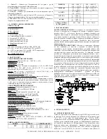
7 - PROBLEMS, MAINTENANCE AND WARRANTY
ERRORS SIGNALLING:
The instrument shows the error message
"EEEE"
, when the probe is interrupted or in overrange, or
"- - - -"
when the probe (PTC, RTD or normalised signals) is in short-circuit or
underrange; in this case verify the correct probe wiring with the
instrument and afterward proceed to verify itself. In the error condition all
the outputs are disactivated.
HOW TO CLEAN
:
We recommend to avoid abrasive cleaners or
containing solvents which could damage the instrument.
WARRANTY AND REPAIRS
:
The instrument is under warranty against
construction vices or defected material, noticed within 12 months from
delivery date.The warranty is limited to the repairs or to the substitution of
the instrument. The eventual opening of the housing, the violation of the
instrument or the wrong use and installation of the product means the
automatically decay of the warranty. In case of defected instrument,
noticed in warranty period or out of warranty, do contact our sales
department to obtain the shipment authorisation. The defected product
must be shipped to TECNOLOGIC with the detailed description of the
failures found and without any fees or charge for Tecnologic, safe
different agreements.
TECNOLOGIC - THP 24
USER MANUAL (I - GB) - Vr. 01 - ISTR 00239 - PAG. 8


