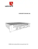
TECNARE MA-2400 Owner'S Manual Download Page 5

Front Panel

£

04

POWER

ON

OFF

Power switch

Press to toggle the power on or off.

Fault

Fault LED

Lights up red to indicate that protection is in effect. Specifically, lights up if the heat sink

overheats, or if a DC voltage is detected at the amplifier outputs. Also lights up for about

Three seconds at time of power-on, as the amp gets ready to operate. To provide protection,

the unit will not output any sound from the speakers while this indicator is lit up. When

Start-up is completed or the problem is corrected, the indicator goes off and normal oper

-ation resumes.

Clip

Clip LED

Lights up orange when the output signal distortion on the corresponding channel rises above

1% -indicating that"clipping" has occurred because the signal level is too high.

-10dB

-30dB

Signal LED

Normal indication:

The -30dB indicator illuminates when the signal exceeds -30dB, and

the -10dB indicator illuminates when the signal exceeds -10dB.

If no iddication:

check gain settings and increase gain if necessary. Check input conn

-ections and audio sourece for signal. If the Clip LED illuminates with little or no Signal

Indication, check the output wiring for shorts.

Abnormal indication:

if -20dB, -10dB LED illuminates with no signal input, there may be

system oscillations or some other malfunction. Disconnect the load and fully reduce the

gain. If the LED remains on , the amp may need servicing.

Power

Power LED

Normal indication:

AC switch ON, LED will illuminate.

If no indication:

Check AC outlet.

Gain Controls

Turn the gain controls clockwise to increase gain and counter clockwise to decrease gain.

The maximum voltage gain of the amplifier varies depending on the model is shown of the

designation. Maximum voltage gain for each model is shown on the front panel label in

parentheses adjacent the 0dB attenuation setting.

The Gain controls are marked in dB of attenuation.There are 21 detents for repeatable

adjustments. The upper 14 steps ate about 1dB each, and settings should normally be

made within this range. The range below -14 dB should not be usde for normal program

levels, as the input headroom could be exceeeded, but can be used for thesting at reduced

levels. At the minimum setting, the signal is completely cut off.

CH-A

!

!

Summary of Contents for MA-2400

Page 1: ...OWNER S MANUAL EXEL Exclusivas Electroacusticas S A ...

Page 2: ...ry contact your dealer Do not modify the unit Doing so is a fire and electrical shock hazard If lightning begins to occur turn off the power switch of the unit as soon as possible and unplug the power cable plug from the electrical outlet If there is a possibility of lightning do not touch the power cable plug if it is still connected doing so may be an electrical shock hazard In case an abnormali...

Page 3: ...free space around the unit for normal ventilation This should be 5cm at the sides 10cm behind and 10cm above If the airflow is not adequate the unit will heat up inside and may cause a fire To relocate the unit rurn the power switch off remove the power plug from the AC outlet and remove all connecting cables Damaged cables may cause fire or electrical shock other than on the dedicated rack shock ...

Page 4: ...emperature Annular big transformer make sure enough powr supply Solid crust alnico panel standard installing hole Working condition under Stereo Bridge Parallel Fault on and audio output automatically stop when protection circuit done Limiting protection on off avoiding lashing DC protection output short circuit protection over heat protection and so on Inside limiter is a very effective protectiv...

Page 5: ... ections and audio sourece for signal If the Clip LED illuminates with little or no Signal Indication check the output wiring for shorts Abnormal indication if 20dB 10dB LED illuminates with no signal input there may be system oscillations or some other malfunction Disconnect the load and fully reduce the gain If the LED remains on the amp may need servicing Power Power LED Normal indication AC sw...

Page 6: ...ble s plugs unconnected is necessary Otherwise when feeding in unbalanced audio signals via PIN3 B cold and PIN2 A hot strange humming and HF interference may occur which very likely will damage the power amplifier and or the connected speaker cabinets NF connection cords Choosing high quality balanced cables two conductors for the audio signal plus sepearate shielding mesh with XLR type connector...

Page 7: ...s independent and each may be used for a different signal Parallel Mode This setting connects both inputs of a pair together One signal feeds both channels Do not connect different sources to each input Each channel s gain control and speaker connection remain independent Bridge Mode This setting combines both channels of a pair into a single channel with twice the output voltage Use only the firs...

Page 8: ...Dimensions Unit MM 410 88 483 20 07 ...

Page 9: ...pping Full power sine is continuous sine wave driven at 1 clipping 08 Specifications MH 4000 8ohm 3300W 4500W 4ohm 1030W 1600W 2200W 2ohm 100V 50V us 80dB 0 1 0 1 0 1 500W 740W 1500W 1 4V 483x390x88mm 23 7kg 26 7kg 106dB AC 230V 50Hz 60Hz Audio limiters high temperature short circuit Front to rear 450 20k balanced 10k unbalanced 20Hz 20kHz 0 2dB Load Impedance Rated output power THD 1 1kHz Maximum...

Reviews: