Adjusting the balancer
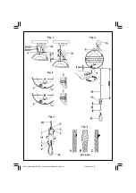
To enable the balancer to balance heavier loads, use the specific key to turn screw 9 (Fig.4) in the direction indicated by symbol “+”. For lighter
loads, turn screw 9 (Fig.4) in the direction indicated by symbol “-”.
After having adjusted the load, check that the cable slides freely for its entire length: the movement must not be restricted when the spring has
wound all the way. Check the stroke often and at different speeds.
NOTE: should the balancer’s capacity of supporting a hanging load decrease, this could mean that the spring of the drum is about
to break. DO NOT MODIFY BALANCER ADJUSTMENT TO MAKE IT HOLD UP THE LOAD IN ALL CASES BUT CONTACT SKILLED
PERSONNEL IN CHARGE OF MAINTENANCE AT ONCE.
Safety devices
Drum spring breakage
The balancer is fitted with a safety device that trips when the drum spring breaks and stops the balancer to prevent the hanging load from
falling.
If the hanging tool cannot be lifted or lowered through ordinary strain, DO NOT INSIST but contact customer service.
NOTE: the balancer stops even if the drum spring is fully discharged: in this condition the head of the charge screw 9 (Fig.4)
protrudes approximately 4 mm outside the cap. To restore operating conditions, try to charge the spring as outlined in paragraph
“Balancer adjustment”. If the balancer does not release, DO NOT do anything and contact customer service.
Manual lock
The balancer is fitted with a manual locking system (Fig.2): push and turn the pin 6 (Fig.2) by 90°(position A) to lock drum rotation; push and turn
the pin 6 (Fig.2) by 90°(position B) to operate as usual.
WARNING: do not leave the balancer with the drum locked and no hanging loads.
WARNING: if the balancer’s cable is not fully wound, and no load is applied to it, DO NOT do anything but contact the customer
service at once.
OPTION “RI”, insulated rotary suspension (Fig.3)
Permits to insulate the load hung on the balancer and/or turn the hanging tool freely without twisting the cable.
WARNING: always comply with the safety regulations when using electrical appliances.
Installation: insert the snap-hook (29) into the pin (E) of the rotary suspension. Insert the cable’s thimble (28) into the pin (F); insert the split-pin
(D) and deform it.
INSPECTIONS AND MAINTENANCE
Maintenance may be carried out only by skilled and authorized personnel.
- Visually inspect the balancer on a regular basis (for instance once at each work shift). Specifically, check the state of the suspensions (33)
and S (Fig.1), the fixing screws & self-locking systems (if used), and the condition of the hooks and cable.
If the cable has the defects shown in (Fig.5), replace it immediately.
Do not make any modification to the cable unit and, specifically, DO NOT SHORTEN the cable: if need, please get in touch with TECNA S.p.A.
- check that the cable’s movement is smooth and that it does not make any strange noises
- do not lubricate the balancer with flammable or volatile fluids
- do not remove any labels. Replace any damaged labels
- the balancer must be inspected at least once a year by skilled, authorized personnel.
Never disassemble the balancer. Maintenance is to be carried out only by skilled, authorized personnel.
The balancer must be disposed of complying with prevailing rules and regulations at the end of its work life.
Warranty
The use of non-original TECNA spare parts will negatively affect safety and performance and will, in any case, void the warranty.
ISTRUZIONI BILANCIATORI_man 9024_9354-9359_05-2010.pmd
13/07/2010, 15.25
5


