1
3
4
2
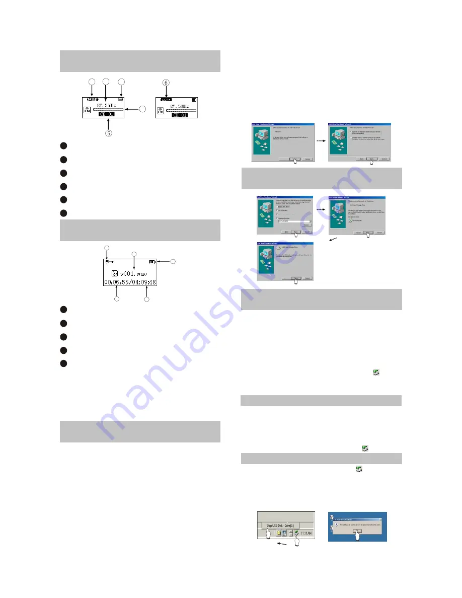
2.1.5 TUNING INTERFACE
ILLUSTRATION
1
PRESET mode (normal receiving)
Frequency of the current radio station
Battery capacity
Frequency bar
PRESET channel display
SCAN mode (scanning)
2
3
4
5
6
1
2
3
4
5
2.1.6 RECORDING INTERFACE
ILLUSTRATION
Name of recorded file
Battery capacity
Time that has been recorded
The left recordable time
Recording state
1
2
3
4
5
As for the name of recorded file
"V001.WAV": 001 is serial number of the current
recorded track and arranged according to
sequence; WAV is file format after recording
2.2 BASIC OPERATION
2.2.1 INSTALL USB DRIVE
PROGRAM
If your computer is Windows 98, you must
install drive program if you want to use the
mobile storage function of MP3 player in
computer.
1. Place USB drive disc into CD-ROM driver of
computer.
2. Connect MP3 player to computer will
automatically indicate that
new firmware device has been found, and run
the installation guide, shown as the following
figure.
You only need to find the drive nformation file
on disc according to prompt information to
finish the installation of drive program.
3. After installation finishes, restart the computer
and you may use the mobile storage function
normally.
Shown as the following figure:
2.2.2 INSTALL USB DRIVE
PROGRAM
2.2.3 USE MOBILE STORAGE
FUNCTION
This player can be used as mobile storage
in Windows ME/2000/XP operating system. In
Windows 98SE and Mac operating system, drive
program must be installed firstly and then used
as mobile storage. Connect Mp3 PLAYER and
computer with USB transmission line. After the
bottom right comer of desktop appears” “
symbol, the mobile storage function of Mp3
PLAYER may be used normally.
NOTE:
# To avoid abnormality of the player appears,
you are suggested to power off firstly before
connecting use USB transmission line to
connect Mp3 PLAYER, then connect computer.
# In Windows 98 system, there is no” “ symbol.
2.2.4 DISCONNECT USB SAFELY
After operation finishes, click” “ symbol
on bottom right corner of Windows desktop with
right button of mouse, and disconnect USB
safely according to the computer prompt.
- 6 -
Summary of Contents for X21
Page 1: ...service manual X21 RU ...
Page 42: ...3 L1 1 8V energy storage waveform diagram 4 LCD_CS wabeform 5 LCD_D C waveform diagram 37 ...
Page 43: ...6 LCD_RESET 7 LCD_WR waveform diagram 8 LCD_RD waveform diagram 38 ...
Page 45: ...12 LCD_DB3 waveform diagram 13 LCD_DB4 waveform diagram 14 LCD_DB5 waveform diagram 40 ...
Page 46: ...15 LCD_DB6 waveform diagram 16 LCD_DB7 waveform diagram 17 IREF waveform diagram 41 ...
Page 47: ...18 VCOMH waveform diagram 42 ...
Page 66: ...Chapter Cinque PCB board Circuit diagram Section One PCB board X21 PCB Board 61 ...


