Keywords: How to use SSD1928, cmos camera interface to SSD1928,
PIC32 interface SSD1928, cmos camera interface to MCU
TechToys Company @ www.TechToys.com.hk
AN020513
Document Rev 02052013
Author John Leung
Page 5
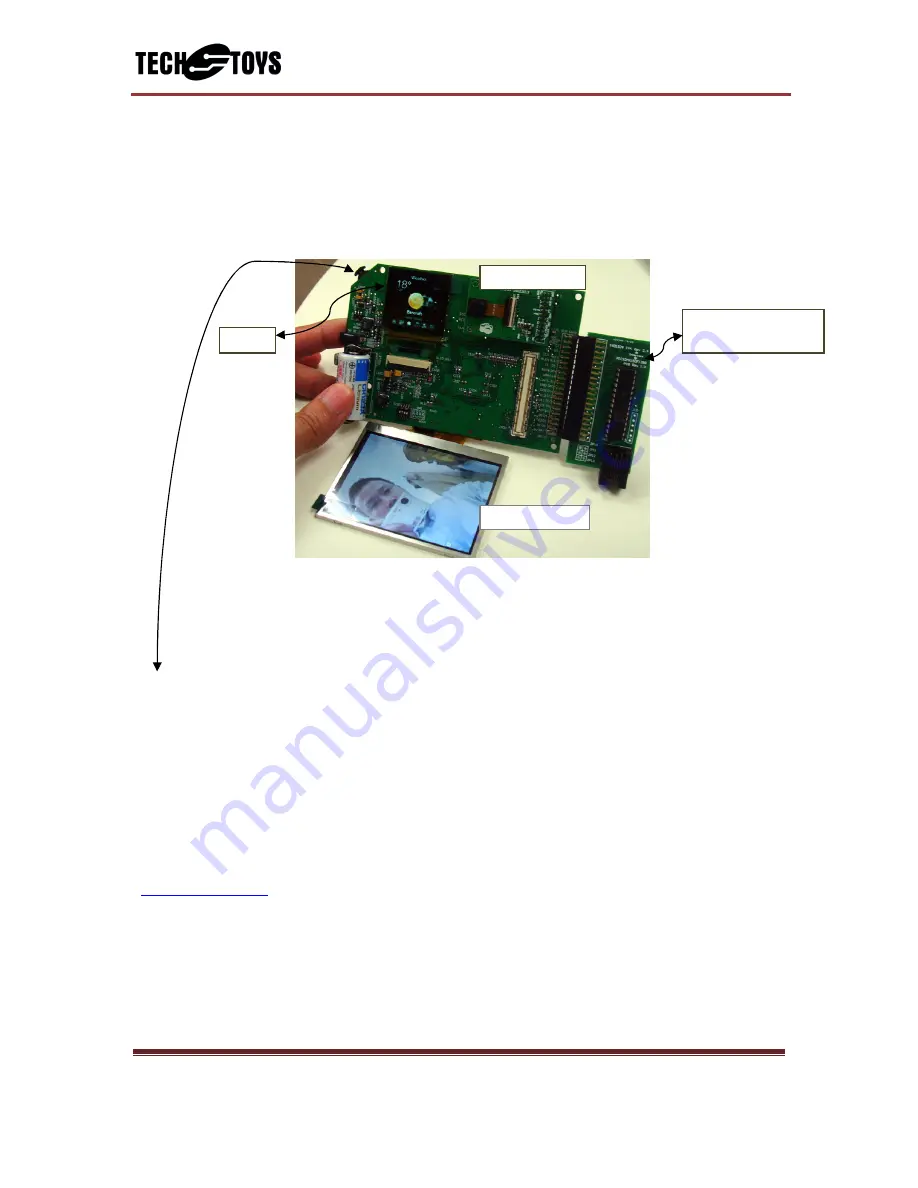
The software starts with displaying a static image on OLED and then capturing a life video
from a cmos camera (optional). Picture below shows a self-portrait with 3V lithium battery
installed. Three cmos sensor models are supported in current firmware version. They are
OmniVision OV965x 1.3Mpixel cmos camera, OV2640 2Mpixel cmos camera, and OV2643
cmos camera. The software distinguishes which cmos sensor has been inserted by reading
the PID register.
Different sensors return different PIDs. The software simply compares the return
value with known values to tell which camera is used. If no camera is in place, the
QVGA screen will display a blank screen.
Pulling the scroll button anti-clockwise will browse to the next file on SD card.
The demo shows JPEG files with *.jpg extension. The unique setup of this demo is that the
JPEG data is not sent back to the MCU, rather, it is buffered and decoded by SSD1928 JPEG
hardware decoder to the frame buffer on the SSD1928 RAM directly. The MCU only
manages the SSD1928 hardware registers and the file system. When displaying a JPEG file,
the SSD1928 frame buffer is set to use the YUV color mode. Resolution of the images must
be less than 2560x1920 (maximum scale down factor supported by the SSD1928 is 8).
The demo will also play video files formatted as RGB565 for each frame. Use ffmpeg
(
http://ffmpeg.org
) to do the video conversion, an example ffmpeg command line that
outputs a video compatible with this demo is:
ffmpeg -i video.avi -s 320x240 -pix_fmt rgb565 video.rgb
The demo attempts to play video files with *.rgb extension. When playing an RGB file, the
SSD1928 frame buffer is set to use the RGB color mode.
CMOS camera
QVGA display
PIC32MX250F128B
MCU board
OLED


