


TD20 Series VFD
Function Parameters
-32-
Function
code
Name
Detailed instruction of parameters
Default
value
Modify
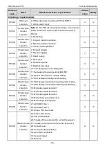
decreases to 0Hz, the VFD stops.
1: Coast to stop: after the stop command becomes valid,
the VFD ceases the output immediately. And the load
coasts to stop at the mechanical inertia.
P01.09
Starting
frequency of
DC braking
Starting frequency of DC braking: start the DC braking
when running frequency reaches starting frequency
determined by P1.09.
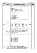
Waiting time before DC braking: VFDs blocks the output
before starting the DC braking. After this waiting time,
the DC braking will be started so as to prevent
over-current fault caused by DC braking at high speed.
DC braking current: the value of P01.11 is the
percentage of rated current of VFD. The bigger the DC
braking current is, the greater the braking torque is.
DC braking time: the retention time of DC braking. If the
time is 0, the DC braking is invalid. The VFD will stop at
the set deceleration time.
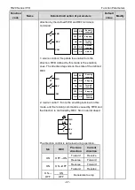
P01.04
ACC
P13.14
P01.23
Constant
speed
In running
DEC
P0110
P13.14
P01.12
P01.09
t
Setting range of P01.09: 0.00Hz
–P00.03
(the Max. frequency)
Setting range of P01.10: 0.00
–50.00s
Setting range of P01.11: 0.0
–100.0%
Setting range of P01.12: 0.00
–50.00s
0.00Hz
○
P01.10
Waiting time
before DC
braking
0.00s
○
P01.11
DC braking
current
0.0%
○
P01.12
DC braking
time
0.00s
○
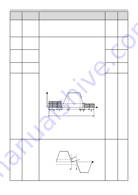
P01.13
Dead time of
FWD/REV
rotation
During the procedure of switching FWD/REV rotation,
set the threshold by P01.14, which is as the table below:
Output frequency
FWD
REV
T
Starting
frequency
Shift after the
Zero frequency
Shift after the
Starting frequency
Setting range: 0.0
–3600.0s
0.0s
○
Summary of Contents for TD20 Series
Page 1: ......
Page 129: ...TD20 Series VFD Appendix C Peripheral Options and Parts 127 PB External brake resistor TD20...
Page 131: ......


