


Annex A SPN of MasterCAN DAC Functional modules / Collector DAC15 FM
MasterCAN DAC J1939 i/o modules. Operation manual. Version 2.0
©
Technoton, 2018
52
—
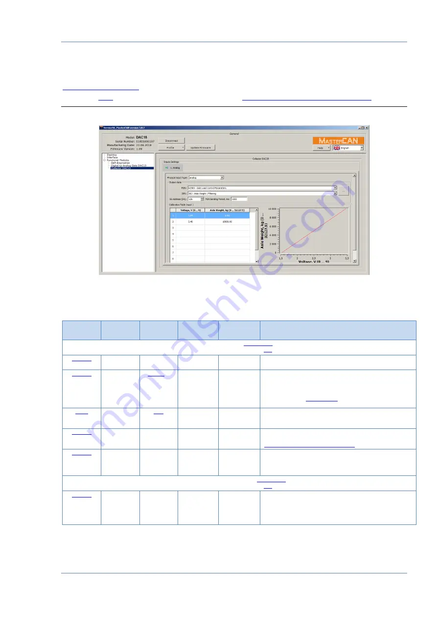
designed to receive an analog signal, to convert it into digital
parameters and to transfer it into
CAN j1939/S6 Telematics interface
*
This FM is created only for MasterCAN DAC15 model.
Figure A.4
—
Window of settings of Collector DAC15 FM in Service S6 MasterCAN software
Table A.3
—
Collector DAC15 FM.
SPNs, displayed and/or editable in Service S6 MasterCAN software
SPN
Name
Factory
value*
Unit
of measure
Data Range
Clarification
Input settings (
Input number
No
No
0…255
Choosing Unit’s contact group I1 of resistive physical
input.
PGN
Axle load control
parameters
No
0…65535
Specifying output PGN which should include SPN
converted from analog or frequency signal.
PGN can be selected in Software from the priority list
containing the most important Vehicle parameters or from
extended list of
SPN
Axle weight
No
0…524287
Selecting SPN, which should be converted from analog
or frequency signal.
S6 Address
(SA)
126
No
0…255
Specifying SA network address of Unit
(MasterCAN DAC15 digital-analog converter) included in
CAN j1939/S6 Telematics interface
PGN sending
period
1000
ms
0…4294970000
Specifying time period (ms) of composed PGN
transmission to CAN j1939/S6 Telematics interface. For
PGN transmitted on request, time period 0ms should be
selected.
Calibration table input 1 (
Physical
input type
Analog
V
(for analog)
Hz
(for frequency)
10…50
(for analog)
10…10000
(for frequency)
Selecting necessary type of physical intput of signal
–
analog or frequency. User can also turn off the output.
In this case settings of the output will not be available
for configuration.