


Technosoft 2018
28
iMOT Intelligent Motors Line Technical Reference
3.11 Recommendations for EtherCAT® Wiring
a) Build EtherCAT® network using UTP (unshielded twisted pair) cables rated CAT5E or higher (CAT6, etc.).
Cables with this rating must have multiple characteristics, as described in TIA/EIA-568-B. Among these are:
impedance, frequency attenuation, cross-talk, return loss, etc.
b) It is acceptable to use STP (shielded twisted pair) or FTP (foil twisted pair) cables, rated CAT5E or higher
(CAT6, etc.). The added shielding is beneficial in reducing the RF (radio-frequency) emissions, improving the
EMC emissions of the application.
c) The maximum length of each network segment must be less than 100 meters.
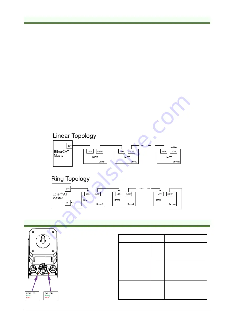
d) The network topology is daisy-chain. All connections are done using point-to-point cables. The global topology
can be one of the two:
•
Linear, when the J2 / OUT port of the last drive in the chain remains not connected. Master is connected to
J1 / IN port of the first drive; J2 / OUT of the first drive is connected to J1 / IN of the following drive; J2 / OUT
of the last drive remains unconnected.
See
Figure 3.8
for a visual representation of the linear topology.
•
Ring, when the J2 / OUT port of the last drive in the chain is connected back to the master controller, on the
2nd port of the master. This topology consists of the linear topology described above, plus an extra
connection between the master, which has two RJ45 ports, to J2 / OUT of the last drive.
See
Figure 3.9
for a visual representation of the ring topology.
e) Ring topology is preferred for its added security, since it is insensitive to one broken cable / connection along
the ring (re-routing of communication is done automatically, so that to avoid the broken cable / connection)
f)
It is highly recommended to use qualified cables, assembled by a specialized manufacturer. When using
CAT5E UTP cables that are manufactured / commissioned / prepared on-site, it is highly recommended to
check the cables. The check should be performed using a dedicated Ethernet cable tester, which verifies more
parameters than simple galvanic continuity (such as cross-talk, attenuation, etc.). The activation of “Link”
indicators will NOT guarantee a stable and reliable connection! This can only be guaranteed by proper quality
of cables used, according to TIA/EIA-568-B specifications.
Figure 3.8.
EtherCAT® network linear topology
Figure 3.9.
EtherCAT® network ring topology
3.12 EtherCAT® LED indicators
Figure 3.10.
LED indicators
Table 3.1
– LED indicators
LED name
LED
color
Function
Drive Ready/ Error
green
Lit after power-on when the
drive initialization ends.
Turned off when an error
occurs.
red
Turned on when the drive
detects an error condition
or when the internal signal
OUT2/Error is set to zero
with OUT(2)=0 TML
instruction.
EtherCAT® LED
red
and
green
EtherCAT® ERROR and
RUN indicators combined.
Shows the state of the
EtherCAT® Status
Machine


