background image

3

Multytenne

EN

FR 

IT

NL

CZ

PL

1  

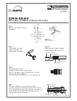
Mounting the external unit

When you unpack the external unit, you will find that it has already been partly pre-assembled, so all 

you need to do is to mount the dish (item 2) and the connector piece (item 3). First, use the screws (A) 

to attach the dish to the AZ/EL bracket (item 1). Then loosen the screw (B) on the swivel profile in order 

to mount the connector piece. Then mount the LNB (item 5) on the LNB holder, using the LNB holding 

bracket (item 6) as shown in illustration 1.

2  

Installation

Selecting a location

a) 

First ensure there is an uninterrupted line of sight from the intended mounting position in a south-

erly direction in order to receive signals from the satellite position ASTRA 19,2° East. With the 

aid of the illustration below you can see whether you have left enough space with regard to any 

neighbouring obstruction, in order to avoid the signal being weakened by such an obstruction. 

When mounting the dish below a terrace, please ensure that it is not in the shadow of a project-

ing roof.

b) 

Now attach the wall mount (item 4) horizontally at the location selected. In order to ensure an 

optimum hold fort he external unit, you should select appropriate fastening materials (dowels, 

screws, etc.). Because of the huge variety of wall conditions found in practice, no fastening mate-

rials for mounting he wall mount is supplied with the package.

c) 

Loosen the screw (C) on the wall mount, and attach the external unit using the connector piece.

Angle A 


Gradient B

(elevation) (cm 

per 

m)


22°    

40,40

24°    

44,52

26°    

48,77

28°    

53,17

29°    

55,40

30°    

57,74

31°    

60,00

32°    

62,49

33°    

64,90

34°    

67,45

35°    

70,02

36°    

72,65

37°    

75,36

38°    

78,13

Summary of Contents for DIGIDISH 33

Page 1: ...EN FR IT NL CZ PL Installation Manual Wall Mounting DigiDish 33 DigiDish 45 Satman 33 Satman 45 Multytenne 45 ...

Page 2: ...n enjoy optimum reception performance after installation Before starting the installation please check that you have received all parts and components of the external unit Items supplied see illustrations 1 and 2 Item Article 1 AZ EL bracket with LNB holding bracket and swivel profile 2 Dish antenna 3 Connector 4 Wall mount short or medium or long 5 LNB 6 LNB holding bracket with 2 screws M3x30 2 ...

Page 3: ... 19 2 East With the aid of the illustration below you can see whether you have left enough space with regard to any neighbouring obstruction in order to avoid the signal being weakened by such an obstruction When mounting the dish below a terrace please ensure that it is not in the shadow of a project ing roof b Now attach the wall mount item 4 horizontally at the location selected In order to ens...

Page 4: ...nector carefully on to the cable until the core cable is level with the front rim of the F connector Then check once more that the wire mesh is not in contact with the core cable The F connector is now correctly mounted Screw on F connector Exposed wire wire mesh Silver foil 5 Positioning the external unit The positioning of the external unit should preferably be done with the aid of a calibration...

Page 5: ... up the transponder information see operating manual of the digital receiver 7 Now carefully adjust the azimuth East West angle as well as the angle of elevation so that the indicator for signal strength resp quality is at a maximum level 8 Now tighten all screws and take care to note that reception does not deteriorate The dish is now completely mounted and has an optimum position fort he recepti...

Page 6: ...t the 4 switching criteria of the DiSEqC control as follows 1 Push the LNB housing onto the twin tube frame and hold it in position by means of the self tap ping internal hexagolnal screw supplied 2 Now use a suitable antenna calibration tool DiSEqC setting A A to position the dish fort he Astra 19 2 East satellite 3 Use a suitable co axial cable to connect the LNB to the digital receiver Note Do ...

Page 7: ...rst remove the foil from the sealing tape 2 Apply one end of the sealing tape approx 1 2 cm below the F connector 3 Now stretch the sealing tape as much as possible and wrap it around the co axial cable and the F connector with overlapping edges Stretching the sealing tape ensures that the layers of tape form a sealed bond at the overlapping edges 4 The LNB is now insulated and sealed so that no w...

Page 8: ... Balcony stand Art No 0000 1751 This product bears the CE symbol and complies with all relevant EU standards Subject to change without prior notice not responsible for printing errors Correct as at 10 04 DigiDish and TechniSat are registered trademarks of TechniSat Digital GmbH Postfach 560 D 54541 Daun Germany www technisat com ...

Reviews: