SJ-MD100
– 13 –
Can ROM
disc be inserted
correctly?
Is disc turning?
NO
YES
NO
YES
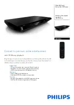
Does output
of IC3 pin 21 alternate
above and below VREF
(1.65 V)?
Is voltage
output between IC2
pins 17 and 18?
Faulty spindle motor
NO
YES
NO
YES
ROM/RAM Operation
NO
3
YES
YES
NO
YES
NO
YES
NO
YES
NO
YES
NO
YES
Voltage alternates above
and below VREF (1.65 V).
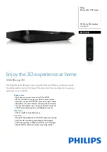
IC10
e
LOAD OPEN SW0 (S3)
t
LOAD PLAY SW2 (S5)
y
LOAD PLAY/REC SW3 (S6)
q
DISC-IN
STOP/PLAY
H
H
L
L
REC
H
L
H
L
H = 3.3V L = 0V
5
NO
IC3 pin 21
Faulty IC3
Faulty IC2
Does optical
pickup move up
and down?
(Continued on next page.)
Does CN4
pin 18 change from
"H" to "L" when disc
is inserted?
Faulty loading
TRG S7
D i s c t r a y
O P E N
L
H
H
H
Is output of
IC10 pins 13, 15, 17,
and 18 OK?
Is voltage
of IC10 pins 8
and 9 OK?
Is voltage
output from IC92
pins 2 and 4?
Faulty loading motor
Faulty S3, S4,
S5, and S6
Faulty IC10
Faulty IC92
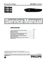
IC3 pin 18
Voltage alternates above
and below VREF (1.65 V).
Faulty IC3
Faulty IC2
Does output
of IC3 pin 18 alternate
above and below
VREF (1.65 V)?
Is voltage
output between IC2
pins 13 and 14?
Faulty optical pickup