


– 38 –
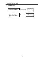
1
2
1
A
B
S
T
R
C
47C
49C
2
4
52C
1Y
47C
5
6
7
8
L1
L2
L3
N
C
FM
L
H
63PH
C
23S
4
5
1
2
3
52C
51C
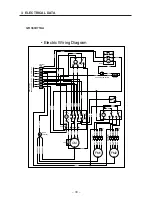
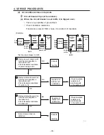
• Schematic Diagram
Symbols Description
CM
FM
52C
51C
49C
47C
63PH
23S
C
1Y
Compressor motor
Fan Motor
Compressor Motor Magnetic Contactor
Compressor Motor Overcurrent Relay
Compressor Motor Thermal Protector
Negative Phase Relay
High Pressure Switch
Fan Speedcontrol Thermostat
Capacitor
Auxiliary Relay
Connector
Terminal Plate
13
14
5
95
96
51C
52C
1Y
3
CM
GR250X7TAA
3. ELECTRICAL DATA


