Thank you for purchasing our product.
MODEL RTA-910TV
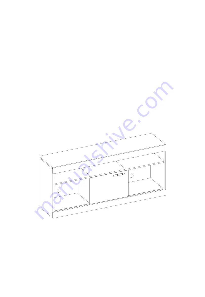
ASSEMBLY INSTRUCTIONS
REV.NTL-6366-0
2
22-0
Page 1: ...Thank you for purchasing our product MODEL RTA 910TV ASSEMBLY INSTRUCTIONS REV NTL 6366 0222 0 ...
Page 2: ...ead carefully the assembly instructions before the installation Do not discard this manual or any of the packaging material until the unit has been completely assembled Might require two people P 1 RTA 910TV P 1 ...
Page 3: ... AND FITTINGS PART QTY ITEM A 30 M6x30 Dowels B 20 M5x31 Bolts C 20 M2x9 Cam locks D 30 ST3 5x12 E 8 ST3 5x40 F 2 ST3 5x25 G 15 Plastic corner bracket H 7 Ø12x6mm Glide studs PART QTY ITEM I 12 Ø15mm Plastic adhesive stickers J 1 128mm Handle K 2 sets Bottom roller with top glide and screws for door L 10 13x13mm Metal junction caps for nails M 50 22 Ø2mm Nails N 1 Touch up chalk NOTE You will need...
Page 4: ...MAIN PARTS LAYOUT FOR REFERENCE P 3 RTA 910TV P 3 7 6 5 6 2 1 1 9 3 3 4 13 8 8 11 10 ...
Page 5: ... assembly using this kind of hardware Cam Bolt Cam Lock 1 Screw the bolt into the corresponding hole on panel A 3 Insert the cam lock on panel B making sure it goes aligned to receive the bolt s head 4 Turn the cam lock clockwise This will lock the parts together and will close any gaps Alignment The cross points towards the panel A with the bolt 2 Join panel B to panel A If panel B comes with the...
Page 6: ...crew bolt or pin might strip the threads or cause damage to the part in which it is being used To avoid misalignments always leave the screws loose and tighten them until all pieces are positioned correctly Sometimes the laminate might cover partially or entirely the hole on a panel If there is no visible hole for the screw pass and press the tip of your finger over the area where the hole should ...
Page 7: ...s 20 Pcs NOT INCLUDED F Bolts 8 Pcs NOT INCLUDED 4 6 All dowels will insert into the innermost holes Top Fr ont Top 2 3 3 Insert the dowels A into the innermost holes on the side edges of panels 1 and 5 Insert the sliding tracks 12 into the grooves on panels 1 and 5 using a rubber mallet but tap gently to avoid breaking them STEP 2 Hardware A Dowels 8 Pcs NOT INCLUDED 1 Front Front 5 6 12 12 ...
Page 8: ...D Cam locks alignment Refer to page 4 4 1 Front Back Top Make sure the sliding track is located at the front on panel 1 Front Assemble the bottom partition panels 3 to the bottom panel 1 with screws E from underneath Top Front Back STEP 4 Hardware E M3 5x40 4 Pcs NOT INCLUDED 1 3 After joined the back of panels 3 will be flushed at the back but receded at the front Front 3 Back Top front on panel ...
Page 9: ...rom this panel Front holes are farther away from the edge STEP 5 Hardware C Cam locks 2 Pcs NOT INCLUDED The Panels 3 will also be receded from panel 5 Assemble panel 2 to panels 1 and 5 with cam locks C as explained in page 4 Top Front STEP 6 Hardware C Cam locks 4 Pcs NOT INCLUDED 1 2 5 4 5 Front Cam locks alignment Refer to page 4 Cam locks alignment Refer to page 4 ...
Page 10: ...th with one bracket G in the middle View from the bottom Front Back STEP 8 Hardware D M3 5x12 9 Pcs NOT INCLUDED 2 1 8 4 STEP 7 Hardware A Dowel 2 Pcs NOT INCLUDED D M3 5x12 15 Pcs G 15 Pcs NOT INCLUDED 13 This middle bracket G installs only on one of of the two panels 8 and facing this way Top Insert dowels A into the indicated holes on the support panel 13 Attach the brackets G to panels 8 and 1...
Page 11: ...p of another person bring the unit upright Secure panel 5 to panels 3 with screws E through the indicated holes Attach the bolts B to panel 5 in the indicated holes STEP 9 Hardware H Glides 5 Pcs NOT INCLUDED STEP 10 Hardware E M3 5x40 4 Pcs B M5x31 Bolts 4 Pcs NOT INCLUDED 4 2 3 5 13 3 8 E B ...
Page 12: ...good alignment of the pieces assemble the other front panel 8 to the top panel 7 with screws D through the brackets G Attach the bolts B to panel 7 in the indicated holes Top Bottom Front Back STEP 11 Hardware B Cam locks 4 Pcs NOT INCLUDED STEP 12 Hardware D M3 25x12 4 Pcs B M5x31 Bolts 8 Pcs NOT INCLUDED 6 6 7 5 Cam locks alignment Refer to page 4 8 ...
Page 13: ...holes on the other side of the door 9 using the own screws that come in the set K Attach the bottom rollers K to the bottom holes with own screws but leave them loose to allow the roller to pivot and make possible to install the door into the unit in the next step STEP 13 Hardware D M3 5x12 2 Pcs B Cam locks 8 Pcs NOT INCLUDED STEP 14 Hardware F M3 5x25 2 Pcs J Handle 1 Pc K x4 sets NOT INCLUDED 7...
Page 14: ...he unit Important The panels don t cover the back completely so make sure to align and center with all sides Use the plates L in between the two panels only Center the nails on the panels if they go too close to the edge of the panel it could split the wood Make sure the nails enter as straight as possible into the panels If they go slanted they could split the wood Front Back STEP 15 Hardware STE...
Page 15: ...on the back You did a great job P 14 RTA 910TV P 14 Attach the stickers I to cover the cam locks If needed use the touch up chalk N to fix any small damages or imperfections on the finish STEP 17 Hardware I Covers 12 Pcs N Touch Up 1 Pc ...
Page 16: ... when moving in the same or adjacent rooms Before moving the unit make sure to secure or remove your TV set or any other objects that are heavy or might fall off Please note that lifting from the top panel with too much weight on the product might lead to part damage separation When lifting the unit use both hands and bend your knees not your backs When transporting the unit to places far away pro...
Page 17: ...t limitations any implied warranty or merchantability or of fitness for a particular purpose Please note all desks made with PVC Laminate surface should not be exposed to direct sunlight as it may damage the material Damage of this nature is not covered under this warranty RTA Products will not be responsible for indirect special incidental or consequential damages This warranty is limited to merc...