P.3
RTA-8404
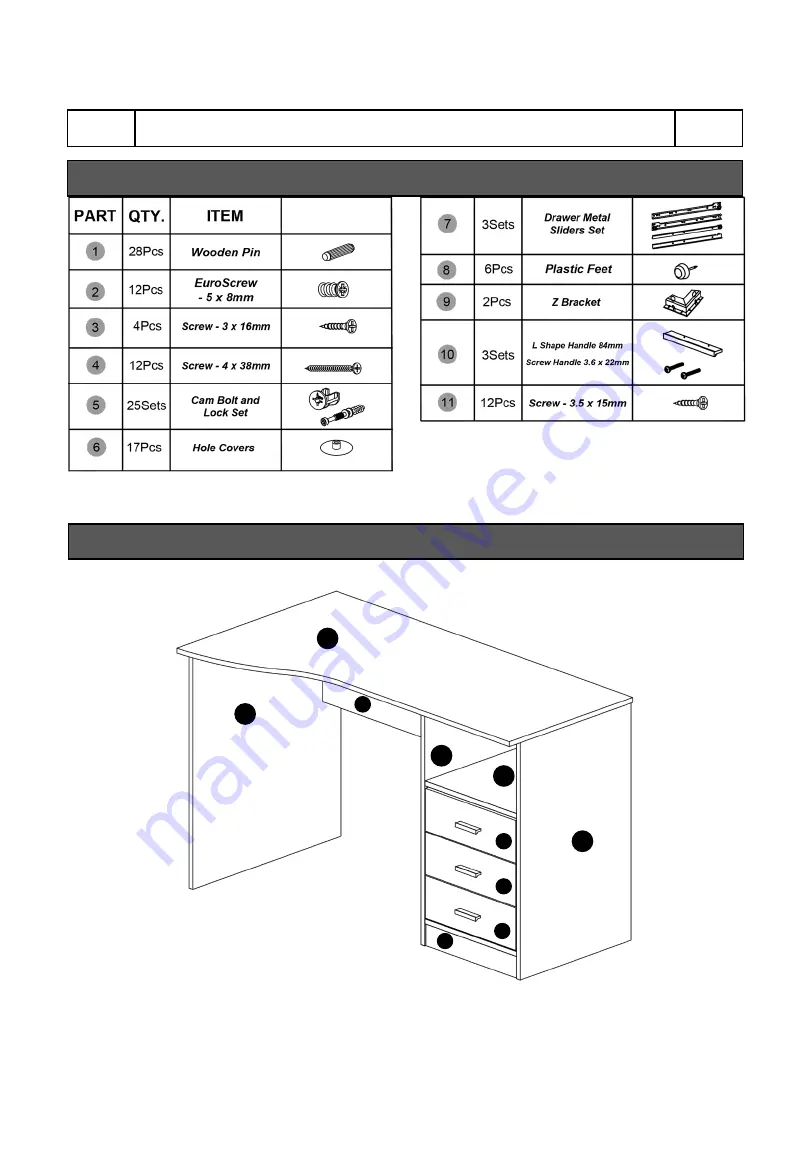
A
C
D
E
F
B
H
I
LIST OF HARDWARE, SCREWS AND FITTINGS
MAIN PARTS LAYOUT (FOR REFERENCE):
Page 1: ...MODEL RTA 8404 ASSEMBLY INSTRUCTIONS Thank you for purchasing our product REV 022021 1 ...
Page 2: ...ead carefully the assembly instructions before the installation P 1 RTA 8404 P 1 Do not discard this manual or any of the packaging material until the unit has been completely assembled Might require two people ...
Page 3: ...top Back Panel Left Panel Right Panel E x1 F x1 G x1 H x3 Middle Panel Partition Panel Bottom Panel Drawer front panel J x3 Leg Panel Drawer left panel K x3 L x3 Drawer right panel M x3 N x1 Drawer back panel Drawer bottom panel Back panel I x1 ...
Page 4: ...P 3 RTA 8404 P 3 A C D E F B H H H I LIST OF HARDWARE SCREWS AND FITTINGS MAIN PARTS LAYOUT FOR REFERENCE ...
Page 5: ...1 Screw the bolt into the corresponding panel 2 Place the other panel over the panel with the bolt then insert the cam lock to join the bolt s head If the cam lock does not want to enter check its proper alignment There might be a very small gap between the panels which is normal 3 Turn the cam lock clockwise This will lock the parts together and will close any gaps Alignment The cross points towa...
Page 6: ...the assembly Do not overtighten or force the screws as they might break strip damage the threads of the holes or get stuck inside the part Make sure you understand which hardware will be used on each step Using the wrong size of screw bolt or pin might strip the threads or cause damage to the part in which it is being used To avoid misalignments always leave the screws loose and tighten them until...
Page 7: ...the wooden pins in subsequent steps Please note that on panel E the bolts are attached on both sides STEP 2 Hardware 25 Pcs STEP 1 Hardware 28 Pcs Insert the wooden pins 1 into the corresponding holes of panels B C D E F G I J and K as shown Make sure to insert in the correct holes as some are intended for other purposes in other steps ATTENTION DO NOT JOIN ANY PARTS IN THIS STEP NOT INCLUDED 5 1 ...
Page 8: ... the flat sliders using screws 2 as shown Please note that the wheel goes toward the front of the panel and there will be 2 holes above the wheel STEP 3 Hardware 12 Pcs 6 Pcs Insert and align the cam locks 5 into the corresponding holes on panel B and assemble to it the panels C and E as shown and as explained in page 4 STEP 4 Hardware 4 Pcs NOT INCLUDED NOT INCLUDED 2 7 Scan QR Code to view this ...
Page 9: ...d align the cam locks 5 into the corresponding holes on panels F and G and assemble them to E as shown and as explained in page 4 Insert back panel N and leg panel I as shown STEP 5 Hardware 4 Pcs STEP 6 NOT INCLUDED 5 TOP FRONT ...
Page 10: ...explained in page 4 Attach the Plastic Feet 8 to the bottom of panels C D and E as shown Insert and align the cam locks 5 into the corresponding holes on panels B C D and E and then with the help of another person assemble the tabletop A as shown and as explained in page 4 STEP 8 Hardware Tools 7 Pcs NOT INCLUDED 5 STEP 7 Hardware 4 Pcs 6 Pcs 5 8 ...
Page 11: ...m locks on the places indicated STEP 9 Hardware 4 Pcs 11 Pcs STEP 10 Hardware 2 Pcs First insert and align the cam locks 5 in the drawer side panels J and K and assemble the panels to the front panel H as shown and as explained in page 4 Then insert the bottom panel M into the grooves of panels J K and H as shown 2 Pcs 3 6 9 NOT INCLUDED 5 ...
Page 12: ...ews 4 as shown Assemble the L shaped sliders 7 to the bottom of the drawer using screws 11 as shown NOTE An incorrect assembly will raise the drawer 1 and will not fit in the desk STEP 11 Hardware Tools 4 Pcs STEP 12 Hardware Tools 4 Pcs 4 NOT INCLUDED 11 J K Scan QR Code to view this step ...
Page 13: ...ver the cam lock holes on panel J and K with 6 as shown Insert the drawers into the cabinet starting with the bottom then middle and finally the top one You might have to insert them at an angle facing down STEP 13 Hardware Tools 1 Set 2 Pcs STEP 14 REPEAT STEPS 10 13 FOR THE OTHER 2 DRAWERS 6 10 ...
Page 14: ...P 13 RTA 8404 P 13 ALL DONE Give yourself a nice pat on the back You did a great job ...
Page 15: ...n 1 feet The unit must be lifted by at least 2 persons when moving in the same or adjacent rooms Before moving the unit make sure to secure or remove any object that is heavy or might fall off Please note that lifting from the tabletop with too much weight on the product might lead to part damage separation When lifting the unit use both hands and bend your knees not your backs When transporting t...
Page 16: ...ed maintained or extended hereunder is in lieu of any and all other warranties express or implied including without limitations any implied warranty or merchantability or of fitness for a particular purpose Please note all desks made with PVC Laminate surface should not be exposed to direct sunlight as it may damage the material Damage of this nature is not covered under this warranty RTA Products...
Page 17: ...P 16 RTA 8404 P 16 ...