background image

- 2 -

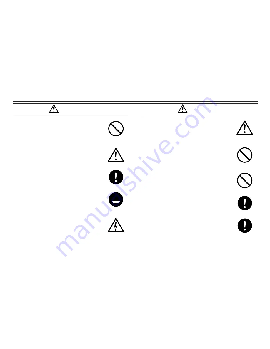
Operating site must be free of water and
humidity.

The pump is not designed to be water-proof or dust-proof.
The use of the pump in places where water splashes or
humidity is high may result in an electrical shock or short
circuit.

Do not damage power cable.

Do not scratch, damage, process, or pull the power cable
forcibly. An extra load onto the cable, such as heating the
cable or placing something heavy on the cable, may dam-
age the cable and finally cause a fire or an electrical shock.

Do not cover the motor.

Running a covered motor may accumulate heat inside the
motor and cause a fire or a mechanical failure. Ventilate
the motor sufficiently.

Arrange grounding.

Do not operate the pump without connecting the grounding
wire. Otherwise, an electrical shock may result. Make sure
the grounding wire is connected with the grounding termi-
nal.

Install an earth leakage breaker (option).

The operation of a pump without using an earth leakage
breaker may cause an electrical shock. Please purchase an
optional leakage breaker and install in the system. 

Prohibited

Power cable cannot be replaced.

Never use a damaged or affected power cable. Otherwise,
a fire or an electrical shock may result. Handle the power
cable carefully, as it cannot to be replaced by a new cable.
(The complete motor must be replaced in that circum-
stance.)

Limited operating site and storage.

Do not install or store the pump in the following places:
* Places where a flammable gas or material is used or

stored.

* Places where the ambient temperature is extremely high

(40°C or higher) or extremely low (0°C or lower).

Do not drain the liquid in the site.

The liquid discharged out of the pump, including a haz-
ardous chemical liquid, must be drained into a special con-
tainer. Never drain such liquid directly onto the floor in or
near the operation site.

Disposal of used pump.

Disposal of used or damaged pumps must be done in
accordance with the relevant local laws and regulations.
(Consult a licensed industrial waste products disposing
company.)

Countermeasure for static electricity.

When low electric conductivity liquid such as ultra-pure
water and flour inactive liquid(e.g.Fluorinert

TM

) are han-

dled,the static electricity may be generated in pump,which
may cause static discharge and break down of pump. Take
countermeasure to avoid and remove static electricity.

Caution

Grounding

Electrical Shock

Caution

Prohibited

Prohibited

Caution

Caution

Summary of Contents for FSSR1

Page 1: ...Issue 1 02 07 FSSR1 Venturi Scrubber Unit OPERATOR S MANUAL ...

Page 2: ... Page 1 Introduction 1 2 Installation 1 3 Start Up 1 4 Normal Operation 1 5 Shut Down 2 6 Maintenance 2 7 Suggested Spares 2 Appendix 1 Scrubber Layout Drawing Appendix 2 Operating and Maintenance Instructions for Pump ...

Page 3: ...ection as labelled it is generally recommended an isolation valve be fitted in the water supply to the scrubber The drain connection may be connected to a suitable drain This is not essential as liquid should not be discharged during normal operation The pump should be connected to a single phase 240V supply DO NOT RUN DRY 3 Start Up Following installation or a shut down period the integrity of th...

Page 4: ...w ready for use The air stream containing the fume to be removed can be vented through the scrubber Over a period of time the recirculation liquid will suffer evaporative losses the operating level will be maintained by the automatic addition of water As the scrubber absorbs and neutralises fumes the scrubbing solution will become contaminated or if added chemical in the scrubbing solution will be...

Page 5: ... at the venturi and above the pump Unbolt the two pairs of metal flanges and remove the venturi Unbolt the tank lid and lift out Lift out the upper mist eliminator grid and eliminator pad Re assembly is reverse of removal carefully ease the inlet pipe through the eliminator pad The unit should be regularly checked for leaks and these should be rectified immediately Inspect the internals on an regu...

Page 6: ...n of more caustic will cause salt build up and blocking of the scrubber the scrubber content should be drained and refilled with fresh solution to prevent this Monitoring of the state of the liquor can be simply carried out using litmus paper or equivalent The caustic solution concentration is not critical we would recommend below 15 and state 5 as a nominal value Caustic soda reacted with HCL giv...

Page 7: ...1 Appendix 1 Scrubber Layout ...

Page 8: ...A3 ...

Page 9: ...Appendix 2 Operating and Maintenance Instructions for Pump ...

Page 10: ...Read this manual before use of product MD SERIES Instruction Manual IWAKI Magnetic Drive Pump ...

Page 11: ...o serious physical injury to the user or serious damage to the product Warning Nonobservance or misapplication of the contents of the Warning section could lead to a serious accident including death or injury Caution Important Instruction Contents Chapter Page 1 Safety Instruction 1 2 2 Unpacking and Inspection 3 3 Operating Principle 3 4 Identification Codes 4 5 5 Specifications 6 7 6 Outer Dimen...

Page 12: ...not limited to chemicals you may experience a serious injury Wear protective gear protective mask gloves etc during the pump operation Electrical Shock Prohibited No Remodeling Wear protective gear Qualified operators only The pump operator and pump operation supervisor must not allow any operators who have little or no knowledge of the pump to run or operate the pump Pump operators must have a so...

Page 13: ... damaged or affected power cable Otherwise a fire or an electrical shock may result Handle the power cable carefully as it cannot to be replaced by a new cable The complete motor must be replaced in that circum stance Limited operating site and storage Do not install or store the pump in the following places Places where a flammable gas or material is used or stored Places where the ambient temper...

Page 14: ... impeller is operated by the magnets The combined coupling torque of the drive magnet and impeller magnet gives sufficient driving power against the motor torque Impeller Suction Discharge Drive magnet Driven magnet Spindle After unpacking the product check the following points If you find any discrepancy please contact your dealer 2P404737 5 Iwaki Magnet Pump MAX CAPACITY MAX HEAD RATED VOLTAGE R...

Page 15: ... symbol Standard type 3 Suction discharge port type M Threaded connection No symbol Hose connection 4 Power source voltage 220 220 240V 50 60Hz 230 230V 50 60Hz 5 O ring material E EPDM No symbol FKM 6 Motor type N New type motor 7 Special spec symbol 01 99 Specially designed specifications No symbol Standard model q w e r t y u ...

Page 16: ... type No symbol Standard type 3 Suction discharge port type M Threaded connection For 50 60Hz 5M Threaded connection For 50Hz only For MD 40RZ 55R 100R No symbol Hose connection For 50 60Hz 4 Special spec symbol 01 99 Specially designed specifications No symbol Standard model ...

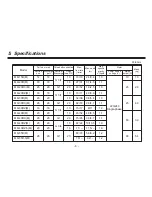
Page 17: ... Single phase 10 1 6 MD 20R M 18 18 16 27 31 3 1 4 3 1 1 20 2 0 MD 20RX M 26 26 G1 20 46 52 1 8 2 5 1 3 MD 20RZ M 18 18 G 3 4 13 10 11 4 9 6 9 1 1 MD 30R M 20 20 16 32 38 3 8 5 4 1 3 45 4 0 MD 30RX M 26 26 G1 20 62 72 2 9 4 1 1 1 MD 30RZ M 18 18 G 3 4 13 15 17 8 11 1 0 MD 40R M 20 20 16 45 52 4 6 6 5 1 1 65 3 9 MD 40RX M 26 26 G1 20 75 85 3 3 4 7 1 1 MD 40RZ M 20 20 G 3 4 16 22 22 10 13 5 1 0 MD 4...

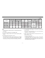
Page 18: ... discharge head 3 Maximum viscosity of liquid 0 03 Pa s for a specific gravity of 1 0 4 Permissible liquid temperature 0 80 C When IWAKI option union is used the liquid temp is limited to 0 55 C Also the permissible temperature may differ depending upon the type of liquid and operating conditions 5 The maximum specific gravity of the liquid is the value at max flow rate The value varies depending ...

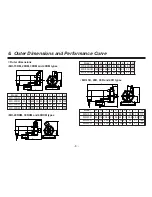
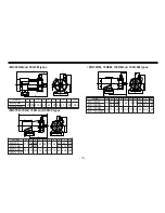
Page 19: ... 48 31 169 MD 40RM 120 130 250 40 64 100 60 48 31 169 MD 20RXM 30RXM and 40RXM types L e a b G c W d H Model W H L a b c d e G MD 20RXM 85 132 220 30 50 68 55 46 5 143 MD 30RXM 120 140 254 40 64 100 60 50 175 MD 40RXM 120 141 256 40 64 100 60 50 175 MD 15R 20R 30R and 40R types Model W H L a b c d e f G MD 15R 95 109 179 5 50 68 55 39 21 5 117 MD 20R 85 115 208 5 30 50 68 55 38 5 28 5 131 5 MD 30R...

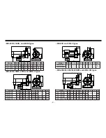
Page 20: ...MD 55R 120 155 273 5 40 64 100 65 61 5 198 5 MD 55R 5 40 MD 20RZM 30RZM 40RZM and 40RZ 5M types L e a b G c W d H f Model W H L a b c d e f G MD 20RZM 85 125 211 30 50 68 55 39 5 38 5 134 MD 30RZM 120 130 230 40 64 100 60 152 MD 40RZM 120 150 241 40 64 100 60 38 5 44 5 160 MD 40RZ 5M 120 150 241 40 64 100 60 38 5 44 5 160 Model W H L a b c d e f G MD 20RZ 85 125 211 30 50 68 55 39 5 38 5 134 MD 30...

Page 21: ...b G c W d H f Model W H L a b c d e f G MD 70R 130 155 258 40 60 110 65 53 43 179 MD 70RZ 165 247 42 47 5 168 MD 100R 156 175 322 70 100 110 75 65 43 5 197 MD 100R 5 MD 70RM 70RZM 100RM and 100R 5M types L e a b G c W d H f Model W H L a b c d e f G MD 70RM 130 155 258 40 60 110 65 53 43 179 MD 70RZM 165 247 42 47 5 168 MD 100RM 156 175 322 70 100 110 75 65 43 5 197 MD 100R 5M ...

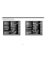
Page 22: ...5 4 3 2 1 1 2 3 4 5 10 20 30 40 50 100 150 200 min 100R 5 M 55R 5 M 100R M 30RZ M 20RZ M 55R M 70R M 40R M 20R M 30R M 40R M 15R M 20RX M 30RX M m 11 10 9 8 7 6 5 4 3 2 1 1 2 3 4 5 10 20 30 40 50 100 150 200 min 100R M 55R M 70R M 40R M 20R M 30R M 40R M 15R M 30RX M 20RX M 30RZ M 20RZ M ...

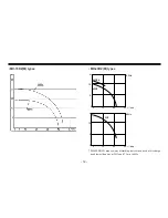
Page 23: ...RZ M types MD 40RZ M types 10 5 10 20 30 0 40RZ 40RZ 5 50Hz m R min 2 10 5 10 20 30 0 60Hz 40RZ m R min 2 MD 40RZ M makes water disturbing noise when used at discharge head lower than 6m at 50Hz and 7 5m at 60Hz ...

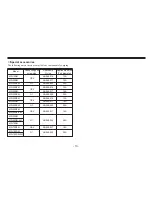
Page 24: ... G3 4 AS 568 016 13A MD 20RM AS 568 017 16A MD 20RXM G1 AS 568 020 20A MD 20RZM G3 4 AS 568 016 13A MD 30RM AS 568 017 16A MD 30RXM G1 AS 568 020 20A MD 30RZM G3 4 AS 568 016 13A MD 40RM AS 568 017 16A MD 40RXM G1 AS 568 020 20A MD 40RZM G3 4 AS 568 017 16A MD 40RZ 5M MD 55RM G1 AS 568 020 20A MD 55RM 5M MD 70RM MD 70RZM G3 4 AS 568 017 16A MD 100RM G1 AS 568 020 20A MD 100RM 5M ...

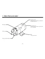
Page 25: ...nit Install the pump at the plate where the liquid can not be splashed Pump unit Liquid feeding unit Discharge port Suction port Base Fix the pump securely Specifications label Use the pump by observing the specifications described on the label ...

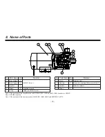
Page 26: ... FKM or EPDM Note 2 No Parts Name Q ty Material 6 Screw 4 6 Stainless steel 7 Bearing 2 Fluororesin containing filler material Note 3 8 Spindle 1 Alumina ceramic 9 Motor 1 Note 1 The material of the impeller used in MD 70RZ MD 100R and MD 100R 5 models is CFRPP Note 2 EPDM is option Note 3 The material of the bearing used in MD 20RZ 30RZ 40RZ and MD 70RZ is PPS ...

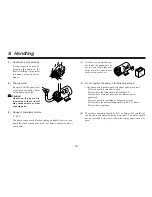
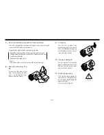
Page 27: ...temperature falls below 0 C Places where corrosive gas such as chlorine gas is generated Places exposed to splashing or dropping of water Places where the ambient temperature is 40 C or above Places where explosive 6 The relative humidity should be 90 or below Be careful not to allow dust and water inside the motor unit The motor should not be splashed with water otherwise it may short circuit or ...

Page 28: ...rry which wears out the pump bearing 8 Keep the pump away from fire To prevent fire and explo sions do not place danger ous or inflammable sub stances near the pump 9 Grounding Be sure to connect the grounding cable green yel low In addition arrange an earth leakage breaker to pre vent electrical shocks 10 If pump is damaged Do not operate a damaged pump otherwise there may happen the electricity ...

Page 29: ...nd generated by the pump is shown in the table Model Sound Level Model Sound Level MD 15R 40 MD 30RX MD 30RZ MD 40R MD 40RX MD 40RZ 60 MD 20R 45 MD 20RX MD 20RZ 50 MD 55R 55 MD 30R 55 75 MD 100R MD 70R 70 dB When measured at a distance of 1m A scale ...

Page 30: ...the suction tank Liquid level must be higher by 30 cm than the pump suction port level If this distance is too short the air may be sucked in the pump which will cause abnormal wear of pump bearing 3 Direction of pump discharge port The discharge port can be directed as desired However for efficient elimination of the air out of the pump chamber it is recommended that the dis charge port is direct...

Page 31: ...e suction side in particular tends to be crushed under the sucking force the use of a braided hose is recommend ed In the case of hot liquid feeding special attention must be paid in the selection of a hose 4 Valve installation Install valves close to the suc tion and discharge port Suction side valve For easy removal or mainte nance of the pump Discharge side valve For adjustment of the dis charg...

Page 32: ... 3 The pump has no On Off switch It starts operation when power is supplied by connecting the power supply cable or other means Wiring diagram MD 15R 20R 20RX 20RZ 30R 30RX and 30RZ models Single phase capacitor run motor with thermal protector Brown Blue Yellow Green Thermal protector Power source Auxiliary coil Capacitor Main coil MD 40R 40RX 40RZ 40RZ 5 55R 55R 5 70R 70RZ 100R and 100R 5 models...

Page 33: ...els 3 phase motor 220 380V Thermal protector Thermal protector Thermal protector Thermal protector Power sauce Power sauce Rotor 220V 380V Red Gray W2 U1 White Blue U2 V1 Black Yellow V2 W1 Red Gray W2 U1 White Blue U2 V1 Black Yellow V2 W1 Thermal protector Thermal protector Power sauce Rotor ...

Page 34: ...5 220 240V Single phase 220 380V 3 phase 400 440V 3 phase 0 3 0 29 0 4 0 4 0 4 0 4 0 4 0 4 1 2 1 25 1 2 1 25 1 1 1 0 1 1 1 0 1 2 1 25 MD 70RZ M MD 100R M MD 100R 5 M 1 2 0 7 1 3 0 8 1 18 0 69 1 17 0 87 1 15 0 64 1 3 0 69 3 8 4 3 3 6 4 0 3 15 3 55 2 9 3 2 3 15 3 42 2 95 3 15 4 15 2 45 4 0 2 4 3 8 2 2 3 7 2 1 3 9 2 25 3 8 2 2 2 15 2 3 2 05 2 27 1 9 2 2 1 85 2 1 1 24 2 27 1 22 1 25 1 93 1 93 1 85 1 8...

Page 35: ...upply When the motor stops rotating the coupling will be connected Operation instructions No 1 2 3 4 Operation Step Check piping wiring and voltage Open and close valves Check that pump chamber is filled with liquid Supply power to pump Description Points to be Checked Check in accordance with the Hose connection and Wiring sections Check the power supply voltage by referring to the information on...

Page 36: ...lf continues to rotate even if impeller is locked In such a case turn off power supply at once When earth leakage breaker is acti vated turn off power supply at once and eliminate cause by referring to Causes of Trouble and Troubleshooting section No 1 2 Stopping Step Close discharge side valve Turn off power supply Check stopping condition Description Close discharge side valve gradually Do not u...

Page 37: ...ble local law or regulation for the handling or disposal of hazardous liquids Draining procedure 1 Turn off the power supply Make sure no other operator will turn on the power supply acci dentally 2 Close the discharge and suction sides valves fully 3 Remove the hoses connected with the discharge port and the suction port Position the draining pan below the pump unit in advance Loosen the hose ban...

Page 38: ... via suction port Pump is driven dry Specific gravity viscosity of liquid is too high Periphery of impeller magnet is in contact with rear casing Impeller is damaged Foreign matter adheres to impeller O ring is damaged Loosened front casing fixing bolts Supply power or contact your dealer Contact your dealer Eliminate air completely Fasten hose tightly Supply priming water to pump Use suitable typ...

Page 39: ...sened Tighten screws with tightening torque not deforming plastic parts When pump is stored for a long time too tighten screws before pump is used Daily inspection Check operating conditions vibration noise and also check electric current value and pump discharge capacity As soon as you find any abnormality turn off power and remove the cause referring to Troubleshooting on page 27 Consumable part...

Page 40: ...not being certified by manufacturer d Repair of failed or damaged product which had been repaired or modified by other person than manufacturer or his representa tive e Repair of failed or damaged product which is caused by fire nat ural disaster or force majeure 3 Manufacturer takes no responsibility for the failure or damage of the product which is manufactured according to the standard or mater...

Page 41: ...803 8807 TEL 886 2 8227 6900 TEL 66 2 320 1303 TEL 852 2 607 1168 TEL 86 20 8435 0603 TEL 86 10 6442 7713 TEL 86 21 6272 7502 TEL 63 2 888 0245 TEL 82 2 3474 0523 FAX 2154 1028 FAX 02 990 42888 FAX 48 24 2346 FAX 8 511 72922 FAX 9 2742715 FAX 66 81 16 61 FAX 1 64 49 92 73 FAX 1743 366507 FAX 32 3226084 FAX 2236 33469 FAX 297 273902 FAX 943 628799 FAX 1430 7008 TEL 49 2154 9254 0 TEL 39 02 990 3931...

Reviews: