background image

TECH

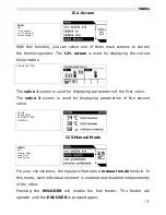
II.4.Screen

With this function, you can select one of three main screens to control 

the thermoregulator. The 

C.H. screen

 is used for displaying the current 

boiler status.

The 

valve 1

 screen is used for displaying parameters of the first valve.

The  

valve   2

  screen   is   used   for   displaying   parameters   of   the   second 

valve.

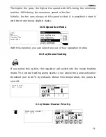
II.5.Manual Mode

For your convenience, the regulator features a 

manual mode

 module. In 

this mode, each individual element is enabled and disabled independently 

of the other.

Pressing   the  

ENCODER

  will   enable   the   fuel   feeder.   The   feeder   will 

operate until the 

ENCODER

 is pressed again.

-7-

MENU

Exit

C.H. Setpoint

H.C.W. Setpoint

Screen Display

HOUSE HEATING

VALVE

VALVE TEMP

SETPOINT TEMP

OPENING

MENU

Exit

Manual Mode

Feed Time

Feed Pause

Summary of Contents for ST-45

Page 1: ...ST 44 USER S MANUAL...

Page 2: ...iant with the Regulation by the Ministry of Economy Journal of Laws Dz U 155 Item 1089 of July 21 2007 implementing provisions of the Low Voltage Directive LVD 2006 95 EC of January 16 2007 The ST 45...

Page 3: ...ns device installation etc All mounting works must only be carried out by qualified electricians Before activating the controller measure the motor resetting efficiency check the boiler and inspect wi...

Page 4: ...been designed and made for comfort It is very easy in use All parameters are adjusted with a convenient knob encoder The ST 45 regulator features also a graphic display that shows the current status o...

Page 5: ...apter describes regulator functionality how to change settings and navigate in the menu with the encoder knob Depending on the mode the boiler is currently in the display will show boiler operational...

Page 6: ...CONFIRM message If you do not wish to make any changes in a given function press the encoder on the CANCEL message II 2 C H Setpoint Temperature With this function you can set the boiler temperature Y...

Page 7: ...r displaying parameters of the second valve II 5 Manual Mode For your convenience the regulator features a manual mode module In this mode each individual element is enabled and disabled independently...

Page 8: ...t the operation time according to the type of fuel and boiler used II 7 Feed Interval With this function you can set the stand by time for the feeder depending on the type of fuel used in the boiler I...

Page 9: ...Mode With this function you can select one out of four operation modes II 9 a House Heating If you select this option the regulator will switch into the house heating mode The central heating pump sta...

Page 10: ...below 62 C to prevent the boiler from overheating Such condition will be maintained until the water heater setpoint temperature is reached When the temperature is reached the hot consumption water pum...

Page 11: ...n the function is enabled the central heating pump is switched off and the hot consumption water pump is activated above the pump activation threshold set to 40 C by default In this mode the hot consu...

Page 12: ...ngs may cause a continuous increase of the temperature Especially the Pause in Sustain Mode should not bee too short II 12 Sustain Mode of Fan In this function you can set the operation time and the p...

Page 13: ...this function you can set the operation time for the mixing three or four way valve only with modules ST 61 For the valve to operate properly and as required it is necessary to set several parameters...

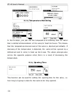
Page 14: ...the valve will be opened by a defined amount in order to heat up the house The above principle also serves the opposite purpose when there is a need of decreasing the temperature III 2 c Opening Time...

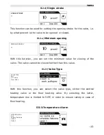
Page 15: ...e valve The valve cannot be closed further than this value III 2 f Valve Type With this function you can select the valve type either the central heating valve or the floor heating valve By selecting...

Page 16: ...igher priority which does not apply to heating from the water heater The feeder fan and central heating pup run until the temperature set with the room regulator is reached However the boiler is limit...

Page 17: ...This is a difference between the setpoint temperature required by the water heater and the actual temperature on the water heater e g when the setpoint temperature is set to 55o C and the hysteresis...

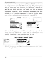
Page 18: ...f The floor heating pump will be re activated when the temperature drops to 2 C III 8 Circulation Pump With this function you can control the pump that is responsible for mixing hot water between the...

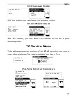
Page 19: ...be able access service functions of the ST 45 controller you need to enter a four digit code The code is available from Sas or Tech IV 1 Pump Switch on Temperature 19 FITTER S MENU Exit Feeder in Aut...

Page 20: ...temperature for the fuel feeder If the feeder temperature rises unexpectedly this can be due to the presence of fire in the feeder After the feeder alarm temperature is reached the feeder starts to r...

Page 21: ...et IV 5 Boiler Alarm Temperature With this function you can set the alarm temperature at which the feeder and the fan will stop and the central heating pump will be activated in order to distribute ho...

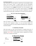
Page 22: ...oiler hysteresis applied IV 7 C H Pump Room Regulator With this function you can switch on or off the central heating pump when the room regulator is active i e you can decide whether the central heat...

Page 23: ...appropriate message Press the encoder to restore the controller to operation VI 1 Temperature Alarm The protection is enabled only in the duty mode i e when the furnace temperature is lower than the...

Page 24: ...is activated regardless of the actual temperature If you press the encoder this refers to the hot consumption water sensor the regulator will deactivate the alarm and the controller will return to its...

Page 25: ...tor When the alarm temperature is exceeded the fan is shut off and both pumps begin to run in order to distribute hot consumption water throughout the system VI 6 Fuel Container Protection At the fuel...

Page 26: ...re committed to protecting the environment Manufacturing electronic devices imposes an obligation of providing for environmentally safe disposal of used electronic components and devices Hence we have...

Page 27: ...5 1 45 80 25 100 6 3 VIII Assembly ATTENTION all assembly works must only be carried out by qualified persons During assembly the device must be disconnected make sure the power cord is unplugged ATTE...

Page 28: ...Controller Particular attention should be paid when making cable connections with the controller Especially the grounding conductor should be connected properly PE GROUND YELLOW GREEN N NEUTRAL BLUE L...

Page 29: ...an 12 III Fitter s Menu 13 III 1 Factory Settings 13 III 2 Valves 1 and 2 13 III 2 a Registration 14 III 2 b Temperature Monitoring 14 III 2 c Opening Time 15 III 2 d Single stroke 15 III 2 e Minimum...

Page 30: ...Mode 23 VI Protections 24 VI 1 Temperature Alarm 24 VI 2 Thermal Protection 24 VI 3 Automatic Sensor Check 25 VI 4 Anti Boil Protection 25 VI 5 Temperature Protection 25 VI 6 Fuel Container Protection...

Page 31: ...TECH 31...

Page 32: ...ST 45 User s Manual 32...

Reviews: