


tech
I. Application
Thermoregulator type ST-431 is intended for operation of three- or
four-way mixing valve with a possibility of connecting additional valve
pump. Optionally, the controller may cooperate with two modules ST-
61, which enables to control altogether three mixing valves. The
controller is equipped with weather control function,1-week program
and may cooperate with the room regulator.
An additional advantage of the device is the protection of
return
temperature
, which fulfils the function of protection against boiling of
the water in the short boiler circulation or against too low temperature
of the water returning to the water boiler.
II
.
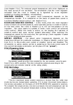
Principle of operation
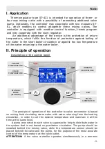
Description of the control panel
The principle of operation of the controller to valve servomotor is based
on mixing feed circulating warm water with water returning from the heating
circulation, in order to set the desired temperature and maintain it all the
time at the same level.
A pump connected to each valve is supposed to help to distribute water in
the system that is not based on gravitation circulation. The pump should be
installed behind the mixing valve, while the temperature sensor should be
placed behind the valve and the pump, for the purpose of the most accurate
control of the temperature at the valve outlet.
ATTENTION
: if the valve controller operates simultaneously in a common
-
5
-
PRESET
TEMPERATURE
VELVE
TEMPERATURE
OPENING
PERCENTAGE
EXIT
PULSE
GENERATOR
STANDBY
MODE
(STANDBY)
Summary of Contents for ST-431
Page 1: ...tech 1...
Page 4: ...ST 431 user manual 4...
Page 21: ...tech Schematic diagram 21...
Page 23: ...tech 23...
Page 24: ...tech 24...