background image

TECH 


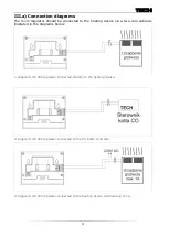
III.a) Connection diagrams 

The room regulator should be connected to the heating device via a two-core cable as 

illustated in the diagrams below:  


1. Diagram: ST-292 regulator connected directly to the heating device. 


2. Diagram: ST-292 regulator connected to the CH boiler controller. 


3. Diagram: ST-293 regulator connected to the heating device with load up to 1A. 


Summary of Contents for ST-29 v1

Page 1: ...ST 292 User s manual 1 User manual ST 292 v1 3 ...

Page 2: ...ce make sure that the user s manual is there with the device so that any potential user has access to essential information about the device The manufacturer does not accept responsibility for any injuries or damage resulting from negligence therefore users are obliged to take the necessary safety measures listed in this manual to protect their lives and property WARNING The device should be insta...

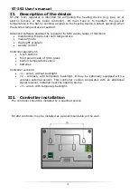
Page 3: ...ntaining the pre set room temperature manual mode day night program weekly control Controller equipment touch buttons front panel made of 3mm glass built in temperature sensor batteries Controller versions v1 wired without backlight v2 wireless with temporary backlight It may be optionally equipped with a wireless external sensor This controller version cooperates with an additional signal receive...

Page 4: ...eating device via a two core cable as illustated in the diagrams below 1 Diagram ST 292 regulator connected directly to the heating device 2 Diagram ST 292 regulator connected to the CH boiler controller 3 Diagram ST 293 regulator connected to the heating device with load up to 1A ...

Page 5: ...ating device with load above 1A 5 Diagram ST 292 room regulator connected to a three phase heating device In the case of wireless connection the diagrams presented above should be used the two core communication cable should be connected to appropriate sockets in the receiver ...

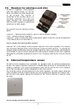
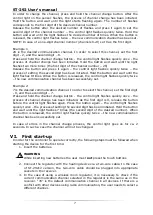
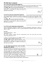
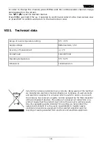
Page 6: ... current channel is used by other devices To change the channel press and hold the channel change button for about 10 seconds until the green control light 1 goes on Next change the communication channel in the room regulator following the procedure described in part V c 10 The green light on the receiver should go off V External temperature sensor ST 292v2 room regulator may optionally be equippe...

Page 7: ...l has been successfully set Example 2 7 is the desired communication channel In order to select this channel set the first digit 0 and the second digit 7 Press and hold the channel change button the control light flashes quickly once the process of channel change has been initiated As the first digit is 0 release the button before the control light flashes again Press the button again the control ...

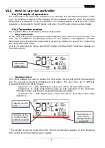
Page 8: ...efine the exact time of entering day mode and night mode In order to activate this mode press EXIT button until day night mode icon appears on the main screen Weekly control This mode enables the user to define the time when the pre set comfort temperature and the pre set economical temperature will apply The user may set 9 different programs divided into three groups programs 1 3 daily temperatur...

Page 9: ... When Day night mode is active the user changes the pre set temperature by pressing which automatically activates manual mode The controller returns to Day night mode when daytime changes into nighttime or the other way round or when the user presses EXIT Example 2 manual mode activation in weekly control mode When weekly control is active the user changes the pre set temperature by pressing which...

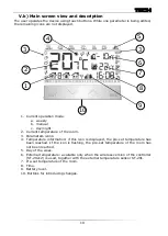
Page 10: ...erature of the room has not been reached 5 Day of the week 6 External temperature available only when the wireless version of the controller ST 292v2 is used together with the external temperature sensor ST 291 7 Pre set temperature of the room 8 Time 9 Battery level 10 Buttons for introducing changes G 1 1 1 1 g g f 1 1 1 1 g 1 G 1 1 1 1 g g f 1 1 1 1 g G 1 1 1 1 g g f 1 1 1 1 g G 1 1 1 1 g g f 1...

Page 11: ...to edit particular parameters press MENU Next press MENU to view the controller functions the edited parameter is flashing whereas the remaining parameters are not displayed Use to change the parameter settings Press MENU to confirm the changes and move on to edit the next parameter or press and EXIT to confirm the changes and return to the main screen view V c 1 Block diagram of the main menu Mai...

Page 12: ...By pressing or set the hour and minute of night mode activation Press MENU to confirm and move on to the next parameter or press EXIT to confirm and return to the main screen view V c 5 Day from This function enables the user to define the exact time of entering the day mode When Day night mode is active comfort temperature applies at daytime To configure this parameter press MENU until Day from s...

Page 13: ...ograms 7 9 In order to edit weekly program press MENU until weekly program setting panel appears on the screen STEP 1 choose the program to be edited By pressing and holding MENU button the user opens the program editing panel Each time the user holds the MENU button the program number changes When the desired number appears on the screen the user may start editing its parameters Step 2 Select day...

Page 14: ... weekly program are displayed at the bottom of the screen hours to which comfort temperature has been assigned are displayed whereas hours to which economical temperature has been assigned are not displayed Example The following screenshot presents daily settings of program no 7 for Monday 24 01 economical temperature 02 06 comfort temperature 07 14 economical temperature 15 21 comfort temperature...

Page 15: ...revent undesired oscillation in case of small temperature fluctuation within the range of 0 2 4 C Example Pre set temperature 23 C Hysteresis 1 C The room regulator reports that the temperature is too low only when the room temperature drops to 22 C In order to set the hysteresis press MENU until the hysteresis setting appears on the screen Use or to set the desired hysteresis value Press MENU to ...

Page 16: ... the natural environment is our priority Being aware of the fact that we manufacture electronic devices obligates us to dispose of used elements and electronic equipment in a manner which is safe for nature As a result the company has received a registry number assigned by the Main Inspector of Environmental Protection The symbol of a crossed out rubbish bin on a product means that the product mus...

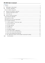
Page 17: ...inciple of operation 8 V b Operation modes 8 V b Main screen view and description 10 V c Controller functions 11 V c 1 Block diagram of the main menu 11 V c 2 Day of the week 12 V c 3 Time settings 12 V c 4 Night from 12 V c 5 Day from 12 V c 6 Weekly program 12 V c 7 Pre set comfort temperature 15 V c 8 Pre set economical temperature 15 V c 9 Pre set temperature hysteresis 15 V c 10 Selecting wir...

Page 18: ... with the Regulation by the Ministry of Economy Journal of Laws 155 Item 1089 of August 21 2007 implementing provisions of the Low Voltage Directive LVD 2006 95 EC of January 16 2007 ST 292 controller has been tested for electromagnetic compatibility EMC with optimal loads applied For compliance assessment harmonized standards were used PN EN 60730 2 9 2011 PN EN 60730 1 2012 Date of CE marking 05...

Page 19: ...ST 292 User s manual 19 ...

Page 20: ...TECH 20 ...

Reviews: