background image

1

G

P

I

:

ENERAL RODUCT NFORMATION

Suitable for damp locations.

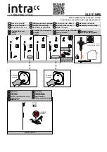
Install the Fixtures

1A

2

1

Ensure that the electrical box is located behind the mirror location.
-For multiple mirror installations, an electrical box must be present behind the mirror which is the center of the group.
-For multiple mirror installations with 600 lms/ft, two electrical boxes must be present behind each outer mirror to support
the additional driver.

Using the provided cardboard mirror template and a fixture; level, measure, and mark the location of mirror(s) and fixtures.

CAUTION - RISK OF FIRE

This product must be installed in accordance with the

applicable installation code by a person familiar with the

construction and operation of the product and the

hazards involved.

Use minimum 90°c supply conductors.

CAUTION:

It is important to determine the location of

the electrical box/driver and fixture layout before
beginning the following installation.

2

5

3

5

3

5

3

MULTIPLE MIRROR INSTALLATION

MULTIPLE MIRROR WITH 600 LMS/F INSTALLATION

1

1

1

2

2

2

B

C

ATH

OLLECTION

5

3

2

1

ELECTRICAL
BOX

CARDBOARD TEMPLATE

36.5”

24”

1.2

Installation Instructions for

Gia Mirror Kit

700BCGIAMR_

920BCGIADM

Summary of Contents for GIA MIRROR KIT

Page 1: ...re level measure and mark the location of mirror s and fixtures CAUTION RISK OF FIRE This product must be installed in accordance with the applicable installation code by a person familiar with the construction and operation of the product and the hazards involved Use minimum 90 c supply conductors CAUTION It is important to determine the location of the electrical box driver and fixture layout be...

Page 2: ... 1C 5 3 At a bracket hole location push the anchor into the wall up to the threads Screw the anchors in the rest of the way with a Phillips head screwdriver Repeat steps 4 5 for the other anchors 2 4 6 6 6 ANCHOR 4 2 5 2 6 1D 5 3 1B 5 3 FIXTURE BRACKET Place the fixture on the marked location and mark the location of the holes in the fixture s mounting bracket Note Ensure that the brackets are loc...

Page 3: ...or 600lms f 2 and 3 mirror Properly connect each of the driver wires to one of the fixture wires in way that the each driver is only connected to a maximum of two fixtures 1G 2 MIRROR WITH 600 LMS F INSTALLATION 3 MIRROR WITH 600 LMS F INSTALLATION 1E 2 8 5 3 9 5 3 Connect the white driver wire to the neutral power line Connect the black driver wire to the hot power line Note For 600 lms f install...

Page 4: ...nnections inside the electrical box If necessary push any excess fixture wire into the electrical box through the mounting plate Attach the mounting plate to the electrical box using the two 8 32 screws provided For 600 lms f installations repeat for the other electrical box 15 16 17 ...

Page 5: ...B 5 3 5 3 4 4 4 At a bracket hole location push the anchor into the wall up to the threads Screw the anchors in the rest of the way with a Phillips head screwdriver Repeat steps 2 3 for the other anchors 2 2 ANCHOR 2 2 3 2 4 5 Replace the mirror bracket bases and secure them by tightening the 8 screw it into the anchors 2C 5 3 5 3 5 5 5 5 5 6 With the provided Allen wrench ensure that the set scre...

Page 6: ... bracket bases Tighten the set screws 2E 5 3 5 3 8 7 8 9 Gently slide the mirror into the assembled lower brackets 2F 5 3 5 3 MIRROR BRACKET MIRROR BRACKET MIRROR 10 Install the top mirror brackets into the bases and tighten the set screws 2G 5 3 5 3 65 ...

Page 7: ...7 ...

Page 8: ...w techlighting com 2014 Tech Lighting L L C All rights reserved The Tech Lighting graphic is a registered trademark of Tech Lighting L L C Tech Lighting reserves the right to change specifications for product improvements without notification A Generation Brands Company 8 ...

Reviews: