


GENERAL INSTALLATION
The DE7288/2005 comes ready assembled, with exception of the alignment mirror and column locking
pedal, which are fitted as follows:
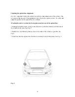
Column Locking Pedal
• Insert brass locking pin through the threaded boss into the column support bearing.
• Fit the pedal assembly in the trolley base as shown in Fig. 5.
• Ensure that the column assembly locks correctly when the pedal is operated. Re-position the pedal if
necessary.
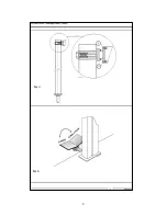
Column
• Holding the column vertically, locate spigot at the base into the column support bearing.
• Check column locks correctly when the pedal is operated.
• Retain column in position with the circular retaining plate and two cap head screws.
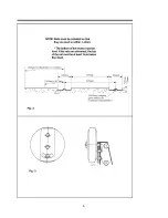
Alignment Mirror
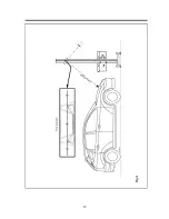
• Fit the mirror assembly in position and tighten the two M4 x 20 screws (1) as shown in Fig. 4.
• Ensure that it rotates smoothly and that the leading edge of the optical box aligns correctly with the line
on the mirror.
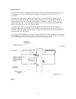
Column Guide
• Tighten the four cap head screws and nuts just sufficiently to remove excessive play.
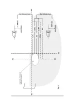
• Tighten the two column guide adjusters just sufficiently to remove side play. (See Fig. 1) Ensure that they
are not over-tightened, so restricting free vertical movement of the optical box.
7