background image


INSTRUCTION MANUAL 

AX48-120 FLANGE FACING MACHINE 

Revision D 


TEAM

® 

Shap Road 

Kendal 

Cumbria 

LA9 6RU 

United Kingdom 

Tel: +44 (0) 1539 729009 

Fax: +44 (0) 1539 729359 


TEAM

® 

is an ISO9001 registered company    


© Copyright 2022 TEAM

®


Summary of Contents for SILK AX48-120

Page 1: ...CTION MANUAL AX48 120 FLANGE FACING MACHINE Revision D TEAM Shap Road Kendal Cumbria LA9 6RU United Kingdom Tel 44 0 1539 729009 Fax 44 0 1539 729359 TEAM is an ISO9001 registered company Copyright 2022 TEAM ...

Page 2: ...ration maintenance and servicing should only be carried out by suitably qualified and experienced personnel The following symbols are used to highlight important areas of this document which relate to potential hazards and residual risks Important statements regarding the use handling or operation of the equipment Warnings to prevent injury to operator and or local personnel Cautions to prevent mi...

Page 3: ... evidence of the purchase date 2 it has been purchased by the user and has not been used for hire purposes 3 it has not been misused or handled carelessly and has been stored and maintained in accordance with any instructions provided by TEAM 4 repairs have not been attempted other than by a member of TEAM service team or by a service provider duly authorised by TEAM to carry out such repairs and ...

Page 4: ...tting up the equipment 24 5 2 1 Unpacking the machine 24 5 2 2 Mounting base installation 26 5 2 3 Centralising the base within the bore 29 5 2 4 Machine installation 30 5 2 5 Setting up the tool 32 5 2 6 Toolpost overrun and gearbox protection device 32 5 2 7 Installing and machine balancing vertical flange 33 5 2 8 Setting up the tool facing and grooving 36 5 3 Using the equipment 37 5 3 1 Conne...

Page 5: ...entraliser 66 8 7 Counter balance 68 APPENDIX A Cutting tools as applied to portable machines 69 APPENDIX B Surface metrology 72 APPENDIX C V Groove measurement 75 APPENDIX D Air motor manufacturers information 77 APPENDIX E Fall Stop Kit 84 1 Technical description 84 2 Specifications 85 3 Safety information 85 4 Installation of the equipment 86 5 Operation of the equipment 88 6 Maintenance instru...

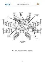
Page 6: ...AX48 120 Flange Facing Machine 5 Fig 1 AX48 120 Flange Facing Machine full assembly Drive motors Surfacing arm assembly Mounting base assembly Feed Gearbox Toolpost Turntable Assembly ...

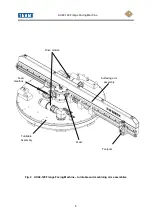
Page 7: ...AX48 120 Flange Facing Machine 6 Fig 2 AX48 120 Flange Facing Machine turntable and machining arm assemblies Drive motors Surfacing arm assembly Mast Toolpost Turntable Assembly Feed Gearbox ...

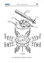
Page 8: ...AX48 120 Flange Facing Machine 7 Fig 3 AX48 120 Flange Facing Machine exploded view Drive motors Surfacing arm assembly Mounting base assembly Feed Gearbox Toolpost Turntable Assembly ...

Page 9: ...ESCRIPTION The AX48 120 Flange Facing Machine is designed to machine full face raised face and grooved flanges from 1220mm to 3048mm 48 to 120 in diameter at any location having a minimum pneumatic air supply of 5 8 m3 m at 6 bar 205 cfm 90 psi The machine can achieve a variety of surface finishes from 6 3μm RA to 1 6μm RA when turning and 1 6μm RA to 0 8μm RA when polishing The machine can also p...

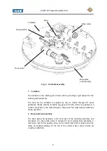
Page 10: ... a central connection on the mast through a rotary seal The mast remains stationary during operation 2 Base plate sub assembly The base plate sub assembly is the fixed part of the turntable assembly and comprises of a base plate which is clamped to the mounting base assembly a mast gear used for the gearbox drive and a central mast which supplies air to the rotary air sealing cartridge At the top ...

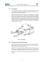
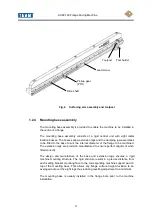
Page 11: ... additional neutral N position is also available by pushing the cutting feed rate selector fully inwards past the No 4 feed position This enables the operator to easily disengage the feed gearbox from any feed Fig 5 Feed gearbox 1 2 3 Surfacing arm assembly and toolpost The surfacing arm assembly is mounted on the turntable assembly and provides a rigid structure to which the tool post is secured ...

Page 12: ...ined The extension legs are precision manufactured to ensure perfect alignment when fitted correctly The design and manufacture of the base and extension legs ensures a rigid machine mounting structure The rigid structure results in a precise distance from each setting bracket mounting face to the corresponding machine support pad on top of the mounting base This allows any flange surface height d...

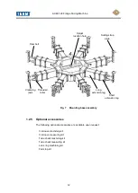
Page 13: ...ng optional accessories are available upon request V Groove machining kit V Groove measuring kit Tube sheet machining kit Tube sheet measuring kit Lens ring machining kit Fall stop kit Setting strap plate Spigot location hole Threaded collar Short extension leg Long extension leg Clamping jaws Ram bolt ...

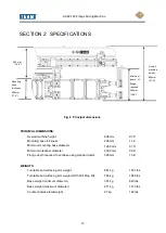
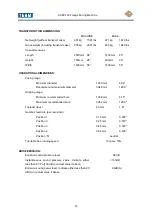
Page 14: ...set base using standard parts Machine height above tube sheet on mounting plate 395 mm 432 mm 15 6 17 0 WEIGHTS Turntable and surfacing arm weight Turntable and surfacing arm weight With Fall Stop Kit 681 kg 765 kg 1501 lbs 1686 lbs Base weight minimum diameter 381 kg 840 lbs Base weight maximum diameter 671 kg 1479 lbs Counter balance total weight 67 kg 148 lbs 405 mm 15 9 Mounting base thickness...

Page 15: ...imum diameter 3048 mm 120 0 Gripping range Minimum recommended bore 1308 mm 51 5 Maximum recommended bore 3052 mm 120 0 Toolpost travel 40 mm 1 6 Gearbox feed rate per revolution Position 1 0 18 mm 0 007 Position 2 0 25 mm 0 010 Position 3 0 46 mm 0 018 Position 4 0 84 mm 0 033 Position N neutral Turntable free running speed 13 rpm 10 NOISE EMISSION Emission sound pressure level 88 dB Instantaneou...

Page 16: ...ne 15 MOTOR INFORMATION Type MODEC MR30LT0133ECL1F Power output 3 0 kW 4 0 hp Maximum speed free running 256 rpm Speed at maximum output 129 rpm 10 Recommended air supply 5 8 m3 min 205 cfm 6 0 bar 90 psi Air inlet thread 3 4 BSP ...

Page 17: ...L TRAINED PERSONNEL WORKING IN AN INDUSTRIAL ENVIRONMENT THIS EQUIPMENT IS INTENDED FOR USE ON METALS AND ANALOGOUS SUBSTANCES THIS EQUIPMENT IS NOT INTENDED FOR USE ON WOOD PLASTIC OR SIMILAR ANALOGOUS SUBSTANCES USE OUTDOORS THIS EQUIPMENT SHOULD NOT BE USED DURING SEVERE WEATHER CONDITIONS PERSONNEL SHOULD NOT OPERATE THIS EQUIPMENT IN WEATHER CONDITIONS WHICH MAY GIVE RISE TO THE FOLLOWING INA...

Page 18: ...APPLICABLE HEALTH AND SAFETY REGULATIONS ALWAYS KNOW THE WEIGHT OF THE EQUIPMENT AND THE COMPONENT PARTS REFER TO THE SPECIFICATION PAGE IN THIS MANUAL OR THE MARKING PLATE ON THE EQUIPMENT THE USE OF MECHANICAL LIFTING DEVICES MAY BE A MANDATORY REQUIREMENT FOR LIFTING THIS EQUIPMENT INSTALLATION AND REMOVAL THIS EQUIPMENT IS INTENDED TO BE PORTABLE AND MAY BE USED IN A VARIETY OF LOCATIONS AND O...

Page 19: ...NOISE AND IMPAIR THE PERFORMANCE OF THE EQUIPMENT NEVER PLACE ANY BODY PARTS ADJACENT TO AN AIR EXHAUST COMPRESSED AIR FORCED INTO THE SKIN IS DANGEROUS AND MAY RESULT IN A SERIOUS SKIN DISORDER ENSURE THE PNEUMATIC SYSTEM IS ISOLATED AND DE PRESSURISED BEFORE MAKING ANY ADJUSTMENTS TO THIS EQUIPMENT ENSURE THE PNEUMATIC SYSTEM IS ISOLATED AND DE PRESSURISED BEFORE DISCONNECTING ANY HOSES DO NOT A...

Page 20: ...e direction of the toolpost as it traverses across the work piece The fully pulled out position N disengages the traverse feed TRAVERSE DIRECTION SELECTOR POSITION TOOL DIRECTION FEED IN selector fully pushed in Towards centre of work piece FEED OUT selector in central position Away from centre of work piece NEUTRAL N selector fully pulled out No movement Traverse direction selector Cutting feed r...

Page 21: ...manufacture Toolpost vertical movement feed knob The toolpost movement feed knob determines the vertical position of the tool and the corresponding depth of cut Turn the hand wheel anti clockwise when looking at the end of the handle to move the tool towards the work piece CUTTING FEED RATE SELECTOR POSITION FEED mm per revolution 1 0 18 mm 0 007 2 0 25 mm 0 010 3 0 46 mm 0 018 4 0 84 mm 0 033 N N...

Page 22: ...t the machine speed at the desired RPM when the control valve is fully open To set the speeds refer to the instructions in section 5 3 1 The filter lubricator oil regulator control is adjusted to provide a lubrication rate of 5 to 6 drops every 1 minute at full motor speed Fig 10 Filter lubricator pack controls ...

Page 23: ...machine when complete and in its packing box weighs 935 kg The machine base when complete and in its packing box weighs 835 kg DO NOT ATTEMPT TO MANUALLY MOVE THE MACHINE OR MACHINE BASE IN THEIR PACKING BOXES ALWAYS USE A MECHANICAL LIFTING DEVICE DO NOT ATTEMPT TO MANUALLY LIFT THE AX48 120 MACHINE OR BASE OUT OF THE PACKING CASE ALWAYS USE A MECHANICAL LIFTING DEVICE WHEN SETTING UP THE MACHINE...

Page 24: ... BY UNAUTHORISED PERSONNEL THIS EQUIPMENT HAS DANGEROUS MOVING PARTS KEEP WELL CLEAR AT ALL TIMES DO NOT ATTEMPT TO MAKE ADJUSTMENTS WHILE THE EQUIPMENT IS OPERATING ALWAYS STOP AND ISOLATE FIRST THIS EQUIPMENT MAY BE USED IN CONJUNCTION WITH OTHER JOB SPECIFIC EQUIPMENT SUCH AS LIFTING ACCESSORIES AND CUTTING TOOLS SUCH EQUIPMENT MUST BE INSPECTED FOR SUITABILITY PRIOR TO USE DO NOT ATTEMPT TO FE...

Page 25: ...ions are for installing the flange facing and grooving machine in position prior to operating the equipment It is assumed that an appropriate air supply is available for connection to the machine 5 8 m3 min 6 0 bar 205 cfm 90 psi 5 2 1 Unpacking the machine Fig 11 Packing case contents ...

Page 26: ...tension legs 8 off 3 Short 175mm extension legs 16 off 4 Dual threaded collar units 8 off 5 Ram bolt thrust washers and jaw assemblies 16 off 6 Setting strap plates 8 off 7 Grub screws for setting strap plates 8 off 8 Setting strap hex section legs 16 off 9 Setting strap leg plate screws 16 off 10 Machine to base securing nut M12 and thick washers 8 off 11 Machine to base M12 studs 8 off 12 Extens...

Page 27: ...ing screws are tight and the assembly is firmly locked together to ensure rigidity during the machining operation CAUTION WHEN LOCATING THE BASE IN A FABRICATED PIPING SYSTEM CHECK FOR ANY WELD BEADS AND FLANGE TO PIPE MISALIGNMENTS WITHIN THE PIPE AND FLANGE BORES THAT COULD PREVENT THE BASE FROM CLAMPING SECURELY 4 Fit the jaw assemblies into the threaded collars 2 per collar Screw the thin lock...

Page 28: ...6mm 2180mm Base unit long external leg collar internal jaw assembly 85 8 92 4 2180mm 2346mm Base unit long external leg collar external jaw assembly 92 4 99 6 2346mm 2530mm Base unit long external leg short external leg collar internal jaw assembly 99 6 106 1 2530mm 2696mm Base unit long external leg short external leg collar external jaw assembly 106 1 113 4 2696mm 2880mm Base unit long external ...

Page 29: ...s Fig 14 Maximum safe distance for jaw assembly extension Setting strap plate Short extension leg Long extension leg Reversible collar mounted externally Ram bolt Setting strap legs hex section Lifting points Levelling grub screw Maximum safe distance 105 mm Setting strap plate ...

Page 30: ...to suit the flange diameter and clamp in position Fit the spike to the outer end of the bar and secure with the socket head screw 2 Using the spike select the datum diameter i e raised face V groove or bolt holes and rotate the clocking arm Check the spike follows the datum and adjust if necessary To adjust the base tighten and slacken opposite sets of ram bolts upper jaws similar to a four jaw ch...

Page 31: ...secure the machine with M12 hex nuts and thick washers Fig 16 5 Although the machine has been designed to be located in the flange bore without the need for levelling it may be necessary when machining flanges with uneven variations in surface height to check the machine is parallel to the flange To check attach and secure a DTI to the toolpost connect the machine to the air supply and set the gea...

Page 32: ...THE AIR FLOW MUST BE REDUCED BY THE GATE VALVE TO RESTRICT THE SPEED OF THE MACHINE Fig 16 Securing machine to base assembly 6 The machine s spigot is designed to centre the machine on the base unit However should the degree of accuracy required be greater the machine can be centred relative to the base by unscrewing the centre spigot from the machine base plate and lightly securing the machine on...

Page 33: ...ected it can be installed in the toolpost and secured by the clamp Tool feed is achieved via the toolpost feed knob which is fitted with a graduated scale divided into metric and imperial increments 5 2 6 Toolpost overrun and gearbox protection device The Toolpost Overrun and Gearbox Protection Device are designed to stop the toolpost leadscrew nut jamming against a fixed surfacing arm end plate a...

Page 34: ...LE TO THE LUG PROVIDED REPLACES ONE EXTENSION LEG REF FIG 17 WARNING WHEN POSITIONING THE BASE WITHIN THE BORE TAKE CARE TO AVOID TRAPPING HANDS OR FINGERS 1 Position the toolpost over the area about to be machined Pass the two threaded studs supplied in the kit through the mounting bosses and secure in a position so that the protruding stud does not foul the work piece as the machine rotates Fig ...

Page 35: ...embly 2 Centralise the base within the bore refer to section 5 2 3 3 Level the machine if necessary i e parallel to the flange refer to section 5 2 4 paragraph 4 When running the following symptoms indicate that the machine is out of balance Uneven arm rotation erratic movement this must be rectified immediately as this may cause damage to the drive system The arm or balance weights make the machi...

Page 36: ...WHEN LIFTING AND POSITIONING THE MAIN COUNTERBALANCE WEIGHT ATTACH THE SUPPLIED LIFTING LUG TO THE THREADED HOLE IN THE WEIGHT AND USE A MECHANICAL LIFT BEFORE OPERATING RECHECK THAT THE BALANCING WEIGHTS AND PLATES ARE FULLY SECURE ON THE MACHINE 4 The flange facing machine is now installed and ready for operation see 5 3 ...

Page 37: ...andard toolpost see Fig 19 select the appropriate tool for the job see Appendix A 3 Install the tool in one of the two positions on the toolpost Tool feed is achieved via the toolpost feed knob 4 With the tool in position check that there are no obstructions to the tool Determine the point at which the tool touches the flange this is achieved by slowly rotating the machine and advancing the tool b...

Page 38: ...to set the machine speed at the desired RPM when the control valve is fully open To set the speeds proceed as follows 1 Observe all Warnings and Cautions refer to Sections 3 and 5 1 2 Set traverse direction selector to N feed disengaged 3 Connect the air lines 4 Close the gate valve and open the control valve 5 Turn on the main air supply 6 Open the gate valve until the desired rotational speed is...

Page 39: ... the required position WARNING THE MACHINE HAS DANGEROUS MOVING PARTS WHEN OPERATED THEREFORE KEEP WELL CLEAR WARNING SHOULD THE AIR SUPPLY FAIL FOR ANY REASON THE OPERATOR MUST SHUT THE AIR CONTROL VALVE SO THAT IT LOCKS IN THE CLOSED POSITION UNTIL THE AIR SUPPLY HAS BEEN RESTORED 8 Start the machine by opening the air supply refer to Section 5 3 1 WARNING DO NOT ATTEMPT TO MAKE ADJUSTMENTS WHIL...

Page 40: ... assembly from the bore ALWAYS USE A MECHANICAL LIFT TO REMOVE THE MACHINE FROM THE FLANGE REMOVE THE MACHINE FROM THE BASE BEFORE LOOSENING THE JAW BOLTS 5 5 STORING THE EQUIPMENT After removing the equipment from the job site the equipment should be thoroughly cleaned and inspected Any faults should be rectified before the equipment is re used or returned to storage After cleaning and inspecting...

Page 41: ...pened 1 Air supply not available Check air supply 2 Air supply is below the minimum required to operate the machine Check air supply 3 Faulty air filter lubrication pack Check operation of gate valve and air control valve 4 Faulty air motor Check operation Refer to manufacturer s literature Replace the motor 5 Faulty gearbox Check operation The machine will not traverse 1 Feed selector incorrectly...

Page 42: ...machine is central 4 Depth of cut too deep Reduce cut 5 Feed rate too high chip thickness too great Reduce tool feed rate 6 Poor tool profile or worn tool Check tool and regrind if necessary 7 Tool and or toolpost not locked in position Check and tighten if required 8 Play in toolpost carriage is too great Check and adjust gib Nil play but free moving 9 Surface arm clamp screws loose Check and tig...

Page 43: ...ould be carried out when specified PERIOD TASK Daily when in use or on completion of a job Clean the equipment Check all components are present refer to packing list in Section 5 2 1 and in good working order Check for correct operation of all the control devices Check all fasteners are properly tight Check and adjust gib strips toolpost and carriage Nil play but free moving Grind the cutting tool...

Page 44: ...nt and check for signs of corrosion or other deterioration Check that all the components are present and in good working order Check main bearing remove turntable and grease main bearing 7 3 RECOMMENDED LUBRICANTS These are the recommended lubricants for the AX48 120 Flange Facing and Grooving Machine Component Lubricant type Product name or specification Air motors Oil Light machine oil Bearings ...

Page 45: ... ALL AIR SUPPLIES ARE REMOVED ISOLATED PRIOR TO WORK COMMENCING 7 4 1 Drive motor To remove 1 Observe all Warnings and Cautions refer to sections 3 1 and 7 4 2 Disconnect the air supply pipe from the motor 3 Slacken the four securing screws which secure the motor to the turntable To refit The procedure for fitting the drive motor is the reverse of the removal procedure Check the drive key is fitte...

Page 46: ...e mounting bracket When the gearbox is clear of the mounting plate it can be detached from the PTO box assembly 9 Draw the gearbox assembly off the location dowels and clear of the input and output support bushes 10 Place in a clean safe location 11 If the drive key becomes displaced it will be necessary to remove the selector shaft and gears To do this remove the black anodised handle and securin...

Page 47: ...Feed Direction black anodised handle by removing the hex locking nut Slide the output shaft with gear out of the gearbox and drift out the broken pin as above 6 Refit the gear and reassemble 7 Check the action of all gear selections and shafts Replace the gearbox and recheck the operation Fig 22 Gearbox shear pins 7 4 4 Surfacing arm To remove 1 Observe all Warnings and Cautions refer to sections ...

Page 48: ...refer to sections 3 1 and 7 4 2 Support the tool post and remove the toolpost stop screw Fig 23 Toolpost stop screw 3 Carefully remove the toolpost assembly from the surfacing arm and place in a safe location 4 If required the toolpost carriage can be removed from the surfacing arm as follows a Slacken gib strip screws b Remove the four screws from the carriage nut c Slide off the carriage and rem...

Page 49: ...ectly without the end plate but if it is not replaced the cast iron dovetail slideway may be damaged To replace the end plate 8 Remove the two end plate mounting studs from the end of the surfacing arm 9 Push the mounting stud through the star washer with the concave side facing the thread 10 Position the end plate and screw the studs back into the slideway POSITION THE ENDPLATE SUCH THAT THAT THE...

Page 50: ...table assembly 51 Surfacing arm assembly 55 Gearbox assembly 58 Base assembly 61 Toolpost assembly 63 Base centraliser 65 Counter balance 67 Fig 25 AX48 120 Flange Facing Machine main assemblies Surfacing arm assembly Mounting base assembly Feed Gearbox Toolpost Turntable Assembly ...

Page 51: ...AX48 120 Flange Facing Machine 50 Fig 26 Mast and turntable assembly sheet 1 ...

Page 52: ...AX48 120 Flange Facing Machine 51 Fig 27 Mast and turntable assembly sheet 2 ...

Page 53: ... MEDIUM 14 FW 0125 1 TOP CLAMP SMALL 15 FW 0126 1 TURNTABLE 16 FW 0143 1 AIR PLUG 17 FW 0144 1 COVER PLATE 18 FW 0533 3 EYEBOLT RING 19 FW 0536 3 LONG COLLAR EYEBOLT 20 CP 0103 1 CENTRE MAST GEAR 21 CP 0105 1 60T GEAR 22 CP 0106 11 SEATING PAD 23 CP 0109 6 CLAMP FACING ARM 24 CP 0111 2 LOCKNUT 25 CP 0120 3 LIFTING BOSS 26 CP 0131 1 CAPTIVE WASHER 27 CP 0132 1 GEARBOX MOUNTING BRACKET 28 CP 0133 1 ...

Page 54: ...COUPLING 0 75 MALE THREAD 51 6 SOC CAP SCR M6 x 20 LG 52 31 SOC CAP SCR M6 x 25 LG 53 2 SOC CAP SCR M6 x 50 LG 54 5 SOC CAP SCR M8 x 25 LG 55 9 SOC CAP SCR M10 x 30 LG 56 9 SOC CAP SCR M10 x 35 LG 57 1 SOC CAP SCR M10 x 45 LG 58 6 SOC CAP SCR M10 x 55 LG 59 3 SOC CAP SCR M10 x 70 LG 60 6 SOC CAP SCR M12 x 50 LG 61 6 SOC CAP SCR M12 x 60 LG 62 40 SOC CAP SCR M16 x 70 LG 63 1 CSK SOC SCR M6 x 16 0 L...

Page 55: ...AX48 120 Flange Facing Machine 54 28 Surfacing arm assembly sheet 1 ...

Page 56: ...AX48 120 Flange Facing Machine 55 Fig 29 Surfacing arm assembly sheet 2 ...

Page 57: ... 1 TRANSFER GEAR 16T 12 CP 0128 1 TRANSFER GEAR 17T 13 CP 0130 2 TRANSFER BOX BUSH 14 CP 0145 1 GIB STRIP 15 CP 0301 1 PLAIN END CAP 16 CP 0302 1 DOVETAIL END CAP 17 CP 0304 2 STRADDLE KEY 18 CP 0305 1 PICKUP GEAR 19 CP 0306 1 CARRIAGE 20 CP 0317 1 LEADSCREW NUT 21 CP 0321 2 SLIDE WAY 22 CP 0323 2 PUSH OFF STUD 23 CP 0819 1 TEAM BADGE 24 CP 0840 1 THIS PART WEIGHS BADGE 25 CP 6000 1 TOOLPOST 26 DE...

Page 58: ...ing Machine 57 37 1 SOC CAP SCR M6 x 25 LG 38 40 SOC CAP SCR M8 x 35 LG 39 5 SOC CAP SCR M16 x 155 40 4 HEX NUT M6 41 4 SOC SET SCR M6 x 25 LG 42 2 CSK SOC SCR M5 x 16 43 2 BRIGHT WASHER M6 44 1 REPAIR WASHER 0 25 x 0 75 ...

Page 59: ...AX48 120 Flange Facing Machine 58 Fig 30 Gearbox assembly ...

Page 60: ... 32T 23 CP 0222 1 INPUT GEAR 24T 24 CP 0223 1 GEAR 20T IN OUT 25 CP 0217A 1 THRUST WASHER 26 CP 0230 1 OUTPUT SHAFT RETAINER 29 CP 0228 1 WORMSHAFT BEARING HOUSING 30 CP 0229 1 CAPTIVE WASHER 31 1 BUSH 1 OD x 3 4 ID x 3 4 LG 32 CP 0275 2 BUSH 1 OD x 3 4 ID x 3 4 LG 33 1 BUSH 3 4 OD x 1 2 ID x 1 2 LG 34 CP 0276 1 BUSH 1 1 8 OD x 7 8 ID x 3 4 LG 35 CP 0277 1 BUSH 5 8 OD x 3 8 ID x 5 8 LG 36 1 BUSH 7...

Page 61: ...R STACK 24T 32T 36T 67 CP 0265 1 30T DRIVE GEAR WITH BOSS 68 1 THRUST WASHER 69 1 SINGLE DIRECTION THRUST BALL BEARING 72 CP 0272 1 40T INPUT GEAR WITH BOSS 73 CP 0273 1 WORMSHAFT 74 CP 0274N 1 INPUT SHAFT 1 2 3 4 N 75 1 EXTERNAL CIRCLIP 16mm 77 2 0 125 DIA ROLL PIN x 1 LG 78 2 SKT SETSCREW DOG POINT M8 x 16 79 2 BUSH 1 OD x 3 4 ID x 3 4 LG 80 CP 0271 1 24T INPUT GEAR WITH BOSS 81 CP 0802 1 LABEL ...

Page 62: ...AX48 120 Flange Facing Machine 61 Fig 31 Base assembly ...

Page 63: ...ETTING STRAP TOP PLATE 10 FW 0517 1 PLATE BUSH CLAMPING MODULE 11 CP 0123 8 M12 THICK WASHER 12 CP 0415 32 VICE JAW 13 16 M36 x 3P THIN HEX NUT 14 16 FEMALE SPHERICAL WASHER 15 8 M12 T NUT 16 8 M12 x 70 LONG STUD 17 8 M12 x 20 LONG DOG POINT GRUB SCREW 18 56 M16 x 35 LONG SOC CAP SCREW 19 96 M16 x 45 LONG SOC CAP SCREW 20 64 M8 x 20 LONG CSK CAP SCREW 21 16 M10 x 25 LONG SOC CAP SCREW 22 8 M12 HEX...

Page 64: ...AX48 120 Flange Facing Machine 63 Fig 32 Toolpost assembly ...

Page 65: ... NUT 10 FXB 0306 1 GIB STRIP 11 AM0812 X 12 1 TOOLPOST BUSH 12 1 M8 NYLOCK TOOLPOST LOCKNUT 13 3 M8 PLAIN WASHER THRUST 14 1 TOOLPOST DOWEL PIN 15 16 5 M6 HEX NUTS 17 1 M6 x 30 SOC CAP SCREW 18 4 M6 x 25 SOC SET SCREW 19 2 M6 x 25 SOC CAP SCREW 20 2 M5 x 0 8 PITCH x 15 21 2 DIA 6 x 25 DOWEL PINS 22 1 M12 x 75 SOC CAP SCREW 23 1 M12 x 50 SOC CAP SCREW 24 CP 0833 1 TOOLPOST WARNING PLATE 25 4 BADGE ...

Page 66: ...AX48 120 Flange Facing Machine 65 Fig 33 Base centraliser ...

Page 67: ...RT No QTY DESCRIPTION 1 FW 10001 1 CLOCKING MAST 2 CP 0140 1 BEARING BLOCK 3 2 TAPER ROLLER BEARING 4 CP 0136 2 BEARING DUST COVER 5 2 M24 x 3 THIN HEX NUT 6 FW 10002 1 PLATE WASHER 7 1 M24 x 3 FULL HEX NUT 8 2 M10 x 25 LONG SOC CAP SCREW 9 FW 0545 1 CLOCKING ARM 10 1 6 x 12 KNUCKLE ...

Page 68: ...AX48 120 Flange Facing Machine 67 Fig 34 Counter balance ...

Page 69: ...RT No QTY DESCRIPTION 1 FW 0531 1 SET BALANCE BLOCKS 2 FW 0532 1 SET BALANCE WEIGHTS 3 FW 0534 1 BALANCE WEIGHT STUD 20 LG 4 FW 0535 1 BALANCE WEIGHT STUD 35 LG 5 4 SOC CAP SCR M12 x 60 LG 6 8 HEX NUT M30 7 8 WASHER M30 8 2 M16 COLLAR EYE BOLT 9 1 SINGLE ENDED OPEN SPANNER 46mm AF ...

Page 70: ...thus lighter and less rigid than its workshop counterpart the choice of tooling and the rate at which metal can be removed will differ from that used in the workshop Each operator has his own favourite tool shape rake and nose radius etc The following gives a general guide to tools and their applications when used on a portable machine ...

Page 71: ...AX48 120 Flange Facing Machine 70 TYPES OF TOOL BIT FOR GENERAL PURPOSE AND FINE FINISH ...

Page 72: ...AX48 120 Flange Facing Machine 71 TOOLS FOR V GROOVE PLUNGE MACHINING ...

Page 73: ...irect indications of magnitude required by workshops Of the usual ways of measuring a wave from the deepest individual roughness depth of surface R Max was too dependent on extremes e g dirt or scratches Conventional statistical terms like RMS present instrumental difficulties The compromise is to use Ra previously known as C L A Centre Line Average which can be determined on a purely geometrical ...

Page 74: ...an line is fitted this allows calculation of some surface parameters Assessment Length Assessment length is the total length of surface to be assessed and is the sum of several sampling lengths L Surface Form Most surfaces are made up of three classes of irregularities These are indicated firstly as a composite surface then as constituent parts ...

Page 75: ...cies of machine such as slideway of arm lift Components of surface finish are like a ploughed field Roughness earth and stones waviness ruts left by the plough form curve of the field The two most common terms now in use are Ra C L A Roughness Average Centre Line Average R M S Root Mean Square The two standards in use today to define these are Metric µm micro meter Imperial 63 Root Mean Square By ...

Page 76: ...AX48 120 Flange Facing Machine 75 APPENDIX C V GROOVE MEASUREMENT ...

Page 77: ...AX48 120 Flange Facing Machine 76 ...

Page 78: ...AX48 120 Flange Facing Machine 77 APPENDIX D AIR MOTOR MANUFACTURERS INFORMATION ...

Page 79: ...AX48 120 Flange Facing Machine 78 ...

Page 80: ...AX48 120 Flange Facing Machine 79 ...

Page 81: ...AX48 120 Flange Facing Machine 80 ...

Page 82: ...AX48 120 Flange Facing Machine 81 ...

Page 83: ...AX48 120 Flange Facing Machine 82 ...

Page 84: ...AX48 120 Flange Facing Machine 83 ...

Page 85: ...f this equipment is to prevent the machine it is fitted to from falling inside a vessel pipe or similar internal opening should the machine and base fixture break loose from the work piece during use This equipment is intended for use only as a safety device when machining flanges or similar components over unobstructed internal openings This equipment is intended for use on the following standard...

Page 86: ...OF THIS EQUIPMENT THIS EQUIPMENT IS FOR USE BY PROFESSIONAL TRAINED PERSONNEL WORKING IN AN INDUSTRIAL ENVIRONMENT THIS EQUIPMENT IS INTENDED FOR USE ONLY ON STANDARD VERSIONS OF THE TEAM AX48 120 FLANGE FACING MACHINE THIS EQUIPMENT IS NOT INTENDED FOR USE ON ANY OTHER MACHINE OR FOR ANY PURPOSE OTHER THAN AS AN FALL STOP SAFETY DEVICE LIFTING ENSURE LIFTING IS CARRIED OUT IN A SAFE AND PROPER MA...

Page 87: ...ED AND RESTRAINED DURING THE INSTALLATION AND REMOVAL PROCESS 4 INSTALLATION OF THE EQUIPMENT INSTALLATION ONTO THE TEAM AX48 120 FLANGE FACING MACHINE Inspect the Fall Stop Kit and confirm that it is complete and fit for purpose FALL STOP KIT Inspect the TEAM machine turntable in the location where the Fall Stop Kit will be installed and remove the 5 socket head cap screws that plug the M16 holes...

Page 88: ... and tighten the fasteners to 60Nm The fasteners should engage in the threaded hole by at least 25mm Severe damage may result if the fasteners protrude within the body of the machine or are tightened against the main bearing Install the bar into the Fall Stop Kit clamp so it is fully retracted Lightly nip the clamping screws to prevent the bar from sliding out of the clamp ...

Page 89: ...n the Fall Stop Kit is not being used the M16 tapped holes in the turntable should be plugged to prevent debris from entering the machine Failure to do this may result in damage to the internal components of the machine Use the fasteners with a thread length of no more than 25mm to plug the M16 holes On completion of the work the Fall Stop Kit must not be removed from the machine turntable until t...

Page 90: ...ecommended that all the tasks should be carried out when specified Period Task On completion of a job and prior to return to storage Visual inspection of all components Replace any worn or damaged parts Protect parts from corrosion Weekly Visual inspection of all components Replace any worn or damaged parts Yearly when not in use Visual inspection of all components ...

Page 91: ...AX48 120 Flange Facing Machine 90 APPENDIX F DECLARATION OF CONFORMITY TEAM Furman House Shap Road Kendal Cumbria LA9 6RU England Tel No 44 0 1539 729009 ...

Reviews: