background image

5

LOSI Tuff COunTry XXX-SCT rTr • InSTruCTIOn manuaL

EN

spektruM dX2l radIo systeM

12

13

11

14

15

16

17

18

10

5

8

1

2

4

9

7

6

3

19

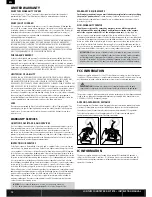
1.  Steering Wheel

 Controls direction (left/right) of the model

2.  Throttle Trigger

 Controls speed and direction (forward/brake/reverse) of the model

3.  r.O.S.S. Button

 Used with vehicles featuring the R.O.S.S. Remote Start System

4.  antenna

 Transmits the signal to the model

5.  On/Off Switch

 Turns the power ON/OFF for the transmitter

6.  Indicator Lights


-

Solid green (right) light

—indicates adequate battery power


-

Flashing green light

—indicates the battery voltage is critically low. Replace batteries


-

Solid red (left) light

—indicates good signal strength. When the red light fades,  

signal strength is weakening

7.  ST. Trim

 Adjusts the “hands off” direction of the model

8.  TH. Trim

 Adjusts the motor speed to stop at neutral

9.  Steering dual rate

 Adjusts the amount the front wheels move  

when the steering wheel is turned left and right

10. Battery Cover

 Covers and holds the batteries that power the transmitter

11. BInd Button

 Puts the transmitter into Bind Mode

12. ST. reV

 Reverses the function of the steering when the wheel is turned left or right

13. TH. reV

 Reverses the function of the speed control when pulled back or pushed forward

14. TH-F


Forward Endpoint

—Adjusts the amount of full throttle

15. TH-B


Brake Endpoint

—Adjusts the amount of full brake

16. ST-L


Steering Left Endpoint

—Adjusts the amount of left steering travel

17. ST-R


Steering Right Endpoint

—Adjusts the amount of right steering travel

18. Throttle Limiter

  Limits the throttle to Low (50%), Medium (75%) or High  

(full throttle is equal to the high Throttle Travel position)

19. Bind plug Compartment

For more information on the transmitter, go to www.horizonhobby.com and click  
on the support tab for the Spektrum DX2L to download the instruction manual.

InSTaLLInG THe TranSmITTer BaTTerIeS

1.  Push in the battery cover a small amount to release the retaining tab,  

then remove the cover.

2.  Install 4 AA batteries, taking care to align the battery polarity to the diagram  

in the transmitter’s battery case.

3.  Carefully reinstall the battery cover by aligning the tabs with the slots on the transmitter. 

 CauTIOn:

 Do not remove the transmitter batteries while the model is powered 

on or while operating, as a loss of model control, damage or injury can result.

5

LOSI Tuff COunTry XXX-SCT rTr • InSTruCTIOn manuaL

Summary of Contents for Tuff Country XXX-SCT Brushless

Page 1: ...cle please read all printed materials thoroughly Horizon Hobby is not responsible for inadvertent errors in this manual Instruction Manual Bedienungsanleitung Manuel d utilisation Manuale di Istruzion...

Page 2: ...uct registration link to stay connected Components 1 10 Scale Tuff Country XXX SCT Brushless RTR Spektrum DX2L 2 4GHz DSM Radio System Dynamite Tazer Waterproof 45A Sensorless Brushless ESC Dynamite T...

Page 3: ...s can reduce the life of the motor The additional resistance of operating in water causes excess strain Alter the gear ratio by using a smaller pinion or larger spur gear This will increase torque and...

Page 4: ...warnings could result in product malfunction electrical issues excessive heat FIRE and ultimately injury and property damage Never leave the charger and battery unattended during use Never attempt to...

Page 5: ...erses the function of the steering when the wheel is turned left or right 13 TH REV Reverses the function of the speed control when pulled back or pushed forward 14 TH F Forward Endpoint Adjusts the a...

Page 6: ...ht 6 Charge the battery 7 Check the calibration of the ESC If recalibration is required follow the setup instructions 8 Check the steering endpoints of the vehicle by turning the steering wheel with t...

Page 7: ...the bearings often If the bearings are dirty they will increase friction and cause reduced performance Keep your vehicle clean and maintained Allow more airflow to the ESC and motor Change the gearing...

Page 8: ...n LED starts to flash 4 Calibrate the throttle points by pressing the SET button once after each step Neutral 1 flash leave the throttle at rest untouched Full throttle 2 flashes pull the throttle ful...

Page 9: ...tight speed could be limited and the motor and ESC will overheat 1 Unscrew the gear cover screws and remove the gear cover 2 Loosen the motor screws and slide the motor back 3 Put a small piece of pap...

Page 10: ...ors of shipping without additional protection Ship via a carrier that provides tracking and insurance for lost or damaged parcels as Horizon is not responsible for merchandise until it arrives and is...

Page 11: ...otects human health and the environment For more information about where you can drop off your waste equipment for recycling please contact your local city office your household waste disposal service...

Reviews: