EN
6
TENACITY-DB PRO RTR, AVC: 1:10 4WD DESERT BUGGY • INSTRUCTION MANUAL
EN
RUN TIME
The largest factor in run time is the capacity of the battery pack. A larger mAh rating increases
the amount of run time experienced.
The condition of a battery pack is also an important factor in both run time and speed.
The battery connectors may become hot during driving. Batteries will lose performance
and capacity over time.
Driving the vehicle from a stop to full speed repeatedly will damage the batteries
and electronics over time. Sudden acceleration will also lead to shorter run times.
TO IMPROVE RUN TIMES
• Keep your vehicle clean and well maintained.
• Allow more airfl ow to the ESC and motor.
• Change the gearing to a lower ratio. A lower ratio decreases the operating temperature
of the electronics. Use a smaller pinion gear or larger spur gear to lower the gear ratio.
• Use a battery pack with a higher mAh rating.
• Use the optimum charger to charge battery packs (Visit your local hobby dealer for
more information).
PERFORMING A CONTROL DIRECTION TEST
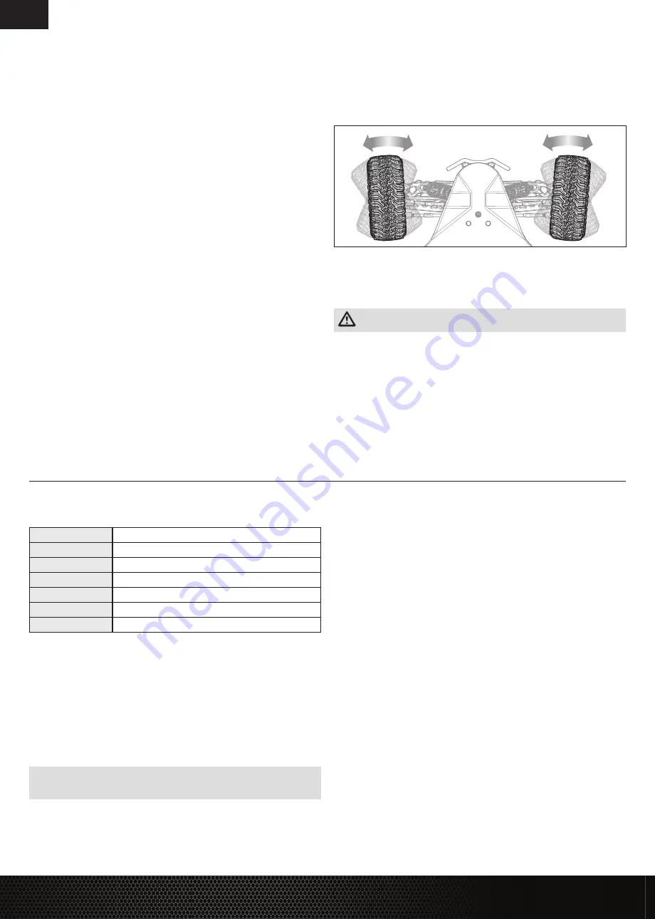
Perform a control test with the vehicle wheels off the ground. If the wheels rotate after the
vehicle is powered ON, adjust the TH Trim knob until they stop. To make the wheels move
forward, pull the trigger. To reverse them, wait for the wheels to stop, then push the trigger.
When moving forward, the wheels should maintain a straight line without any steering wheel
input. If not, adjust the ST Trim knob, so the wheels maintain a straight line without having to
turn the steering wheel.
CHANGING THE TRAVEL ADJUST SETTINGS
Set the travel adjust settings with all four vehicle wheels off the ground. The throttle end point
and brake end point adjustments will cause the wheels to spin at full speed. Have an assistant
safely hold the vehicle securely while adjusting these settings.
CAUTION:
Keep hands, hair and all loose clothing away from any moving parts,
especially the wheels, while setting the travel adjust end points. Serious injury may result.
1. Hold the trigger in the full brake position and turn the steering wheel to full right while powering
on the transmitter. The LED fl ashes rapidly, indicating programming mode is active.
2. Throttle End Point: Continue holding full throttle. Turn the TH TRIM knob to adjust the full
throttle end point.
3. Brake End Point: Hold the trigger in the full brake position. Turn the TH TRIM knob to adjust
the full brake end point. Return the trigger to the center position.
4. Left Steering End Point: Hold the steering wheel in the full left position. Turn the ST TRIM
knob to adjust the left end point.
5. Right Steering End Point: Hold the steering wheel in the full right position. Turn the ST TRIM
knob to adjust the right end point. Return the steering wheel to the center position.
6. Power off the transmitter to save the travel adjust settings.
The minimum Travel is 75%, and the Maximum travel is 150%.
IMPORTANT:
If the travel is changed on the DX2E, you must rebind and calibrate the SRS6100AT.
SPECIFICATIONS
Type
Sensorless, SMART Throttle Compatible
Output
130A/760A
Function
Forward/Brake–Forward/Brake Reverse
Input Voltage
7.4V–14.8V
(The motor in this vehicle will not support 14.8V)
BEC Output
6V/4A
Dimensions (LxWxH)
57.5mm x 46mm x 38mm
Weight
154 g
ESC LED STATUS
• No ESC LEDs will glow when there is no throttle input from the transmitter.
• The red ESC LED glows when there is any throttle input from the transmitter.
AUDIBLE WARNING TONES
1. Input
Voltage:
The ESC checks the in put voltage when it is powered ON. If a voltage
problem is detected, the ESC continuously sounds 2 beeps with a 1 second pause
(xx-xx-xx). Power OFF the ESC and ensure the connections are secure and that
the battery power is not too low for safe operation.
2. Radio
Connection:
The ESC checks radio signal input when it is powered ON.
If a problem is detected, the ESC continuously sounds 1 beep with a 2 second pause
(x--x--x). Power OFF the ESC and ensure the radio system is operating correctly.
NOTICE:
Always disconnect the battery from the ESC after operating your vehicle. The ESC’s
switch only controls power to the receiver and servos. The ESC will continue to draw current when
connected to the battery, resulting in possible damage to the battery through over discharge.
ESC CALIBRATION PROCEDURE
Complete the transmitter/receiver binding procedure prior to calibrating the ESC.
1. Set the transmitter throttle channel to 100% travel and center the throttle trim.
2. Connect a battery to the ESC battery lead.
3. Power on the transmitter.
4. Press and hold the SET button while turning on the ESC. Release the SET button when
the
red
LED begins to fl ash, indicating the ESC is in calibration mode. The ESC will enter
programming mode if the button is held for more than three seconds.
TIP:
The red LED should be fl ashing when the ESC enters calibration mode. If the green LED
is fl ashing the ESC has entered programming mode. Power off the ESC and repeat step 4,
releasing the SET button when the red LED begins to fl ash.
5. With the transmitter throttle trigger at the neutral position, press and release the ESC SET
button. The red LED will stop fl ashing, the green LED will fl ash one time and the motor will
make a tone to indicate the neutral position has been accepted.
6. While holding the throttle trigger at the full throttle position, press and release the ESC SET
button. The green LED will fl ash twice and the motor will make two tones to indicate the full
throttle position has been accepted.
7. While holding the throttle trigger at the full brake position, press and release the SET button.
The green LED will fl ash three times and the motor will make three tones to indicate the full
brake position has been accepted.
The motor will operate normally after calibration is completed.
SPEKTRUM
™
FIRMA
™
SMART 130A BRUSHLESS ESC (SPMXSE1130)


