background image

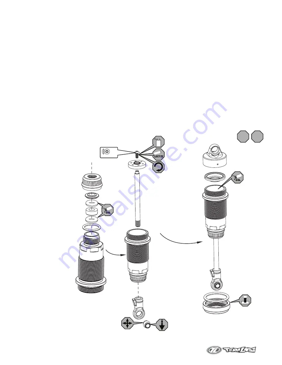
Clean the 2-56 x 1/4” button head screw and apply loctite to the threads.

Install the #55 shock piston using the 2-56 x 1/4” button screw into the shock shaft with a .050” allen wrench.

Place a drop of Shock Oil into the bottom of the Shock Body to lubricate the Shock Seals.

Thread the shock shaft into the shock end using pliers. Use caution when threading the shock shaft ends onto the shafts. Avoid gouging or scratching the shock 

shaft while gripping the shock shaft with pliers by placing the edge of a towel over the shaft, then gripping the portion of the shaft covered by the towel.  This method 

will work very well to protect the shock shafts from damage.

Ensure the shaft is fully extended when filling the shock.

Fill the shock body with 35wt. shock oil until the oil is to the top of the body.

“Work” the shock shaft up and down a few times. 

This will release the air bubbles trapped beneath the piston. Place the filled shock, in the upright position, o

ff to the side 

for a few minutes until the air bubbles escape from the oil.

Once all the air bubbles are out of the oil, gently place the shock bladder onto the shock as shown. Some oil should “bleed” from the shock.

Screw the shock cap onto the body until some resistance is felt.

Slowly push the shock shaft up. This will bleed excess oil from the shock.

Tighten the cap all the way down using the shock tools included in your kit

.

Move the shock shaft up and down. The shaft should be easy to push up into the body of the shock. If increased pressure is felt towards the top, there is to much oil in 

the shock. Loosen the shock cap and “bleed” the shock as done previously.

Make sure each pair (front/rear) shocks have the same rebound and compression. This is checked by holding one shock in each hand horizontally and pushing them 

together by the shock end. Watch carefully to ensure that both compress evenly. Now release both shocks and again watch carefully as they should rebound the same.


Rebuilding/Refilling the Shocks

Rebuilding/Refilling the Shocks

Page 9

2-56 x 1/4”

x 1

x2 x2

Front

Rear

Summary of Contents for 8ight RTR

Page 1: ...40 setscrews on the sway bar ball ends and remove the ball ends from the sway bar Remove four 5 40 flathead screws from the rear clip fig 8 Slide the pivot support and rear diff cover off of the bulkhead and remove the diff fig 9 9 8 RemovingThe Center Differential To remove the center differential the radio tray on your 8IGHT RTR has to be removed 10 Front 11 Turn on the transmitter and receiver ...

Page 2: ... 5 50 x 3 8 button head screws from the center top brace fig 14 Slide the front and rear brake rotor assemblies off of the center diff fig 15 NOTE There are two different size brake discs The large disc is in the front brake assembly and the small disc is in the rear brake assembly Page 7 13 Diff Service Refer to exploded views on page 8 Remove the four 3mm flat head screws from the ring gear allo...

Page 3: ...2 3 4 Center Differential Front Rear Differentials 1 2 3 4 Fill with 5000cs oil front or 2000cs oil rear just above the planetary gear Fill with 7000cs oil just above the planetary gear Tighten the diff screws in this order Tighten the diff screws in this order ...

Page 4: ...d shock in the upright position off to the side for a few minutes until the air bubbles escape from the oil Once all the air bubbles are out of the oil gently place the shock bladder onto the shock as shown Some oil should bleed from the shock Screw the shock cap onto the body until some resistance is felt Slowly push the shock shaft up This will bleed excess oil from the shock Tighten the cap all...

Page 5: ... Guide Initial Factory Settings Steering Tie Rods 3 62 92 00mm Page 10 Camber Links x5 Engine Hi Speed Needle 4 turns out Low Speed Needle 2 5 turns out x 4 x2 5 Team Losi 35wt Shock Oil LOSA5225 Shocks 94 50mm 3 72 Front Camber Link 103 4mm 4 07 Rear Camber Link ...

Page 6: ...s in drive train Rebuild Engine overheats Hi Speed fuel mixture is too lean Low Speed fuel mixture too lean Spoiled or improper fuel Cooling air is being blocked Excessive load on the engine See Understanding Rich and Lean Clean head fins Check for binds Engine hesitates or stumbles Engine overheated Hi Speed mixture too lean Low Speed mixture to rich Air bubbles in fuel line Glow plug fouled See ...

Page 7: ...Operations Guide TeamLosi AdivisionofHorizonHobbyInc Not Responsible For Errors All prices subject to change without notice 800 0317 ...

Page 8: ...izon Hobby shall not be liable for any loss or damages whether direct indirect special incidental or consequential arising from the use misuse or abuse of this product or any product required to operate it This is still a model don t expect it to do unrealistic stunts Warnings Fuel is dangerous if handled carelessly Follow all directions and precautions on the fuel container Keep fuel and all chem...

Page 9: ...eration A lean mixture also makes the engine run hotter than desired and does not provide enough lubrication for the internal engine components causing premature wear and damage It is always advisable to run the engine slightly rich and never lean to avoid overheating and possible damage Engine Break In and Adjustments Breaking in your new engine is critical for proper performance Failure to follo...

Page 10: ...ld the fuel line near the carburetor cutting off the flow of fuel and listen closely to the engine RPM speed If the low speed needle is set correctly the engine speed will increase only slightly and then die If the engine increases several hundred RPM before stopping the low speed needle is to rich Lean the mixture by turning the needle clockwise one hour and trying again If the engine speed does ...

Page 11: ...eing wet with fuel or the element burned out Use a spare glow plug to check the igniter If the igniter makes the element glow remove the plug from the engine to check it in the same manner A wet glow plug means there is excess fuel in the engine To eliminate this put a rag over the head and turn the engine over a few seconds with your Spin Start Reinstall the glow plug making sure you have the bra...

Page 12: ...f the steering wheel to reposition the throttle servo and close the carburetor and apply more brakes Note that additional braking force is applied when you push the trigger forward Maintenance In addition to the service needs pointed out in this guide you should try to maintain your new buggy for proper performance and to prevent wear If dirt gets in the moving parts it can seriously hinder the pe...

Reviews: