CABLES
To adjust the standard cable operating the spools, undo
the two socket head cap screws securing the clamp
plate to the valve. Undo the lock nut on the end of the
cable and rotate the adapter tube until the spool
operates correctly.
To adjust the flow control cable, remove the actuator
handle from the mounting bracket by partly removing the
3 long studs. Release the cable lock nut at the valve
adapter end and rotate the actuator and cable outer 1
complete turn. Operate the bed chain to check the
required adjustment has been achieved before
reassembling the actuator into the mounting bracket.
HYDRAULIC VALVE
Before attempting to dismantle any of the hydraulic
system, the tailgate and deflectors must be fully
lowered to prevent injury from the unexpected
lowering of these components.
To split the valve slices, withdraw the three long studs
through the valve. The positions of the seals are shown
in the parts book diagram. When reassembling the
valve, the studs should be tightened to a torque of 13.5
Nm (10 lb.ft). If over tightened then the spools may jam.
If contaminated oil enters the bypass valve in the flow
control slice, it may jam open causing the hydraulic
circuit to fail. The bypass valve is found on the lower
sloping face of the flow control valve below the pressure
relief valve. To clear the blockage, undo the cap,
carefully making sure the return spring is not lost. Using
a pair of long nosed pliers withdraw the spool from the
valve body. Clear any contamination and refit the spool,
which should move freely. Refit the return spring and
cap.
Contamination may also jam open the pressure relief
valve in the flow control slice. To clear, remove the relief
valve from the body and clear any contamination.
SLIP CLUTCH
If the clutch slips repeatedly for no apparent reason
there are a number of things to be checked:
Firstly check that the clutch linings do not show signs of
damage or excessive wear. If so, they should be
replaced. When new they are 3mm. (1/8") thick.
Also make sure that the compressed spring length is set
to give the correct torque setting – see PTO shaft parts
list.
If the clutch continues to slip it should be adjusted as
follows.
1. Remove the guard fitted to the rotor gearbox.
2. Fit the PTO shaft with the slip clutch at the machine
end.
3. Insert a piece of wood through the discharge chute
and position it such that it prevents the rotor from
turning.
4 Insert a steel bar through the rear PTO yoke and use
a spring balance to obtain the correct torque setting.
The clutch should just slip at a torque of 1200 Nm.
(900 lb.ft.) - equal to a force of 1000N. at 1.2 metre
(225 lb. at 4 feet) from the centre of the yoke. Adjust
the clutch as necessary using the eight spring loaded
clamp bolts.
WHEEL REPLACEMENT
If it is necessary to remove a wheel, place a jack
underneath the axle beam, loosen the wheel nuts and
raise the machine until the wheel can be removed.
Place an axle stand underneath the machine before
removing the wheel. Refit the wheel and tighten the
wheel nuts.
WHEEL NUTS
Before using a new machine and daily during use, check
the wheel nuts are tight. The recommended torque is
shown in table 3.
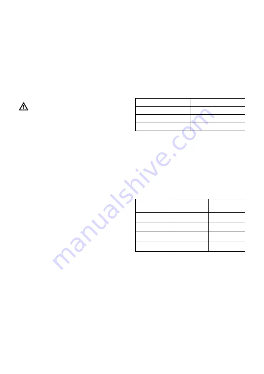
Table 3. Wheel nut torque settings.
Once the nuts are allowed to work loose, it may be
found impossible to keep them tight and new nuts and
studs will be required to overcome the problem. In
extreme cases, damage to the wheel rims and hubs
may result.
TYRE PRESSURES
Check tyre pressures regularly inflating to the pressures
shown in the following table. Over inflation can be
dangerous.
Table 4. Tyre Pressures.
LUBRICATION
Good quality semi-solid grease should be applied to the
following grease points:
Every 4 weeks:
Oil PTO shaft spring plungers
Every 2 weeks:
Swivel chute ring gear (4 nipples)
PTO shaft joints - (2 nipples)
PTO guard bearings (where fitted)
PTO shaft sliding members
Twice weekly:
Bed chain bearings (4 nipples)
Crossbeater bearings (4 nipples)
Shearbolt sprocket bearing (1 nipple)
Bale restraint pivot bearings (2 nipples)
Wheel stud size
Torque Nm (lb.ft)
8080 ( 5 stud )
200 ( 150 )
8080 ( 6 Stud )
400 ( 320 )
9090 ( 6 Stud )
400 ( 320 )
Tyre Size
8080 Pressure
bar (psi)
9090 Pressure
bar (psi)
10.0/80-12
2.4 ( 35 )
- - - - -
10.0/75-15.3
2.0 ( 29 )
- - - - -
11.5/80-15.3
1.2 ( 17 )
5.0 ( 73 )
12.5/80-15.3
1.2 ( 17 )
5.2 ( 75 )
9
Summary of Contents for Tomahawk 8080S
Page 34: ...32 HYDRAULIC HOSES...


