15
Maxim
™
III
Security Alert Interface
Security Alert Feature
Effective for shipments after this date of new or reprogrammed units.
Serial numbers beginning with A19 and later (letter or number is A, B,
C… and number is 19, 20, …).The Maxim™ III security alert feature,
when triggered by an IRT-60 sapphire mic on Channel A, creates a
relay contact closure or opening. The back panel connection is a
normally closed and normally open terminal paired with the common
terminal as shown to the right.
Note:
the wireless microphone channel B does not trigger security alert.
Pulse mode:
The Maxim™ III may be set to provide
either 4- or 1-pulse
signal at the relay. This new feature allows
the user to change from 1 to 4 pulses, or 4 to 1 pulse. Different monitoring systems may require one or
the other.
The steps below describe how to select either the 1-pulse or 4-pulse mode and how to
determine/confirm the Maxim™ III’s selected mode.
Ordinarily, the Maxim™ III will arrive new with the 4-pulse mode selected by default. Installers should
nevertheless confirm the mode upon installation if the security alert feature will be employed. Once set,
the mode is active and should remain set until such time as it is manually changed as detailed below.
The output on the amplifier is a three pin COM, N/O, N/C contact closure labeled “SECURITY ALERT”.
To check the mode:
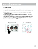
Note the LED color on the power button at the TL logo.
•
If power state is ON (Blue LED at power button), press once to set power state OFF (Red LED).
•
If Red, then you may start the process.
1.
Press and hold the power button (in Red state) for the entire process.
2.
After 4 seconds, the LED will change colors.
3.
Note the number of RED flashes AFTER the GREEN flash.
If one
RED
after
GREEN
, then mode is 1-pulse mode. (This will repeat 3 times.)
G R G R G R
If four
RED
after
GREEN
, then mode is 4-pulse mode. (This will occur 1 time.)
G R R R R
The important part of the sequence is the number of red flashes that follow one green flash.
4.
Release the power button.


