background image

-3-

Important Safety Instructions

17.Power Lines
An outside antenna system should not be located
in the vicinity of overhead power lines or other
electric light or power circuits, or where it can fall
into such power lines or circuits. When installing an
outside antenna system, extreme care should be
taken to keep from touching such power lines or
circuits as contact with them might be fatal
.
18.Overloading
Do not overload wall outlets, extension cords, or
integral convenience receptacles as this can result
in a risk of fire or electric shock.

19.Object and Liquid Entry
Never push objects of any kind into this product
through openings as they may touch dangerous
voltage points or short-out parts that could result in
a fire or electric shock. Never spill any kind of liquid
on the product.

20.Replacement Parts
When replacement parts are required, be sure the
service technician has used replacement parts
specified by the manufacturer or have the same
characteristics as the original part. Unauthorized
substitutions may result in fire, electric shock, or
other hazards.

21.Safety Check
Upon completion of any service or repairs to this
product, ask the service technician to perform
safety checks to determine that the product is in
proper operating condition.

22.Wall or Ceiling Mounting
The product should be mounted to a wall or ceiling
only as recommended by the manufacturer. Any
mounting of the product should follow the
manufacturer instructions, and should use a
mounting accessory recommended by the
manufacturer.

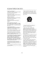
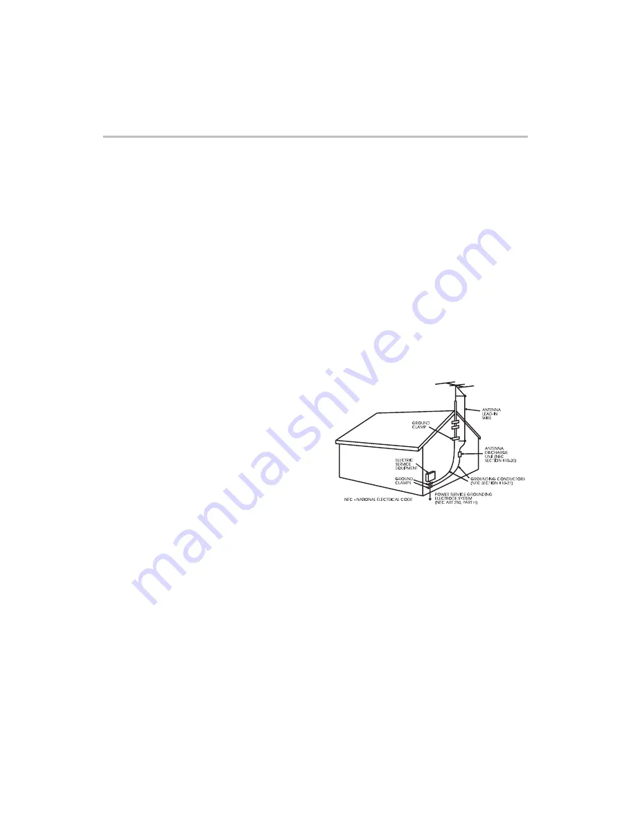
23.Outdoor Antenna Grounding
If an outside antenna or cable system is connected
to the product, be sure the antenna or cable
system is grounded so as to provide some
protection against voltage surges and built-up static
charges. Article 810 of the National Electrical Code,
ANSI/NFPA 70, provides information with regard to
proper grounding of the mast and supporting
structure, grounding of the lead-in wire to an
antenna discharge unit, size of grounding
conductors, location of antenna discharge unit,
connection to grounding electrodes, and
requirements for the grounding electrode. See
figure below.

Summary of Contents for LCD2033A

Page 1: ...WARRANTY INFORMATION INSIDE PLEASE READ WWW TEAC COM AU USER MANUAL 20 LCD TV LCD2033A IMPORTANT ...

Page 2: ... cases of in transit damages or loss a claim must be filed against the carrier by the purchaser 7 In home service will only be provided as part of this warranty if all the following conditions are met a The product is a Colour Television of 51cm screen size or over b The product is within the warranty period C The product is located within the normal service area of the local TEAC Service Provider...

Page 3: ...ice Centre 3 Please have your purchase receipt as your proof of purchase and the following details completed for a valid Warranty Owner s Name Owner s Address Postcode Model Name No Serial No Dealer s Name Dealer s Address Postcode 4 Please ensure that your product is packed appropriately upon return to the service centre If you have any other queries regarding service or warranty please contact t...

Page 4: ...autions Important Safety Instructions i Front Panel Description ii Back Panel Description 25 26 Troubleshooting And Maintenance Display Mode Specifications 15 Connection ii YPbPr YCbCr component Connection i Antenna Connection vi AV Out Connection iii Rear Video Composite Connection V VGA Connection 12 15 24 v Setting Menu 6 Accessory List 16 Button Instruction 17 iv Side S Video and Video Composi...

Page 5: ...______ DON T PLACE TO WET LOCATION Apparatus shall not be exposed to dripping or splashing with water and do not place objects filled with liquids on the apparatus such as vases This equipment generates uses and can radiate radio frequency energy and if not installed and used in accordance with the instruction manual may cause harmful interference to radio communications However there is no guaran...

Page 6: ...fit into your outlet consult an electrician for replacement of the obsolete outlet 10 Protect the power cord from being walked on or pinched particularly at plugs convenience receptacles and the point where they exit from the apparatus 11 Only use attachments and accessories specified by the manufacturer 12 Use only with the cart stand tripod bracket or table specified by the manufacturer or sold ...

Page 7: ...aracteristics as the original part Unauthorized substitutions may result in fire electric shock or other hazards 21 Safety Check Upon completion of any service or repairs to this product ask the service technician to perform safety checks to determine that the product is in proper operating condition 22 Wall or Ceiling Mounting The product should be mounted to a wall or ceiling only as recommended...

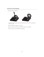
Page 8: ...ith a cushion or other soft materials to protect the screen 2 Remove all cables connected on the TV Monitor 3 Remove the four screws and then remove the stand from the LCD TV Monitor 4 Now you are ready to install Wall Arm mounting device Please follow the instructions given 4 ...

Page 9: ...t or damage caused by the use of parts and accessories manufactured by other companies To avoid malfunction and overheating make sure that the vents on the main unit are not blocked when installing to ensure proper heat emission Distance the unit slightly from other equipment Do not mount the unit flush against the walls etc As show below Do not fit the unit inside narrow spaces where ventilation ...

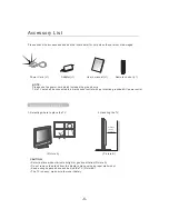
Page 10: ...tective grounded AC power outlet User s manual 1 User s manual Remote control 1 Where to place the TV 1 Selecting where to place the TV CAUTION Select a place without direct sunlight or good ventilation Do not remove the stand from the display unless using a proper wall mount Keep enough space above and behind the TV The TV is heavy make sure to move it safely Picture A Picture B 2 Handling the TV...

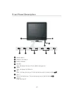
Page 11: ...RCE Press it to display the menu of the available viewing source MENU Press it to display the OSD menu CH VOL Press it to adjust volume The two buttons also act as direction buttons Power on off the TV POWER Press it to choose the channel The two buttons also act as direction buttons 8 4 5 6 7 1 3 2 1 ...

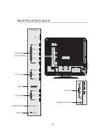
Page 12: ... 8 Back Panel Description SERVICE ONLY UPDATE Headphone Output AV2 Input AV1 Input AV Output SERVICE ONLY Antenna Power Component In HDTV DVD VGA AUDIO IN ...

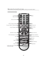
Page 13: ...l To select different viewing signals Enter OSD setup mode MUTE Exit Enter Sound mode Picture mode Next previous channel Zoom in out Aspect Rotate Stop Play Pause Volume up down Dual sound selection To set sleep power off time Page up and down Nine pictures Function No picture To freeze current image These buttons are not available without card reader ...

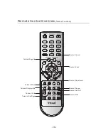
Page 14: ...ol Overview Teletext Functions 10 Teletext Cancel Teletext Index Teletext PageDown Teletext List Flof Teletext Reveal Teletext Size Teletext SubPage Teletext Hold Teletext Store Teletext Display Mix Teletext PageUp ...

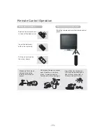
Page 15: ...e are no objects between the remote control and its sensor Don t place the remote control near a heater or in a damp place A strong impact on remote control may damage it Signal from the remote con trol may be disturbed by sun light or other strong light In this case darken the room Insert the batteries with correct polarity Point the remote control at the remote control sensor 30 30 ...

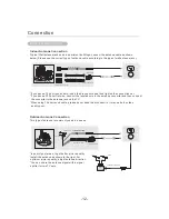
Page 16: ...e converter to the antenna jack on the TV When using 75 ohm round cable please do not bend the bronze wire it may make the video quality poor This type of antenna is commonly used in a house Bronze Wire Wall Connection Jack Outdoor Antenna Connection In poor signal areas to get better picture quality install the antenna as shown to the right You can share the antenna signal with a signal splitter ...

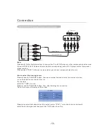
Page 17: ...inishing the connection The source menu will display on the screen Please use numerical buttons directly to select source r use the direction buttons to select the desire signal and then press the OK button to confirm YPbPr o Note Please refer to the illustration above to connect the TV with DVD player or other component signal sources Connect YPbPr YCbCr Cable and Audio Cable to corresponding jac...

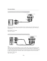
Page 18: ...1 in the source menu when you connect DVD player or other source Note 1 Please refer to the illustration above to connect TV with S Video or other composite signal sources Connect S Video composite video cable and audio cable to corresponding jacks of DVD player or other composite signal sources Please select AV2 in the source menu when you connect DVD player 2 When S Video and composite video are...

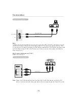
Page 19: ...er to the illustration above on how to connect the LCD TV with PC or DVD player Connect VGA Cable and Audio Cable to the corresponding jacks of PC and select the signal source as VGA 2 If you connect VGA Cable to disc player or Set Top Box please select VGA and set the output mode as VGA Please choose VGA in the Source menu when you connect disc player or Set Top Box with VGA source out Please ref...

Page 20: ...7 8 9 0 MNO PQRS TUV WXYZ ABC DEF GHI JKL Press VOL button to increase the volume Press VOL button to decrease the volume Volume adjustment Numerical button In TV mode press CH button to select next channel and press CH button to select prior channel To select a one digit channel Press from 0 9 to directly input your desired channel number To select a two digit channel Press from 1 9 to input the ...

Page 21: ...ser Standard Soft Bright Close video Sleep timer set up VIDEO OFF Press this button to enjoy music without video Press again to recover video Press SLEEP button to set the sleep time 0 10 20 30 60 90 120 180 240 minutes SLEEP ASPECT Press ASPECT button on the remote control to select your favorite mode Aspect Sound mode adjustment Press Sound button to select your favorite mode Four options Standa...

Page 22: ...ress buttons to change the setting C Press EXIT button to quit In User mode you can adjust Bass Treble Sound Mode Press buttons to sound mode change the Five options Standard Soft Music Cinema User Bass Selected item button button Treble Decrease audio from the right speaker Decrease audio from the left speaker For weaker treble For weaker bass For stronger bass For stronger treble Balance Only i ...

Page 23: ...Sound System Channel Blue Screen Channel Preset Exchange Skip Channel Current Channel Channel Preset Channel Blue Screen Skip Channel Exchange Sound System Current Channel Sound System Channel Blue Screen Skip Channel Exchange Channel Preset Off Off Off Off Off Off 20 20 20 D K D K D K Channel Channel Channel Press button to enter Channel Preset Press button to enter the sub menu Auto Search All c...

Page 24: ...hannel 12 first Input 1 with the numerical buttons in Channel Exchange window You can exchange the current channel with another channel Press the MENU button to select Channel menu Press the MENU button to select Channel menu Press the buttons to select Exchange Channel Press the button to enter this menu 1 1 4 2 3 Current Channel Exchange channel Press buttons to select Blue Screen 2 Press button...

Page 25: ...ue Screen Exchange Skip Channel Off Off 20 Auto Channel Skip Channel You can adjust the aspect as your desired Auto adjust To verify the H Position V Position Phase Frequency automatically Press MENU button to select Window menu Press buttons to change the setting Press buttons to select Aspect Ratio Aspect Ratio Frequency To adjust the horizontal frequency of the image Phase To adjust the image p...

Page 26: ...Temperature Sleep Timer Teletext Language OSD Language OSD Background Color Temperature Sleep Timer Teletext Language OSD Position OSD Language OSD Position Color Temperature Sleep Timer Teletext Language OSD Background English English English 0 Minute 0 Minute 0 Minute Top Left Top Left Top Left West European West European West European Setting Setting Setting Press EXIT button to exit Press EXIT...

Page 27: ...witching to standby automatically You can select 0 10 20 30 60 90 120 180 240 minutes Press buttons to enter the sub menu Press buttons to select Color Temperature Press EXIT button to exit 5 4 Four options Normal Warm Cold User In User mode you can change the R G B parameter to get your desired setting User Red Green Blue 36 34 32 Color Temperature Sleep Timer Teletext Language Press MENU button ...

Page 28: ... of the screen If TOP or FLOF teletext FASTEXT is transmitted by the station by pressing the corresponding colour button on the remote controller you can select the desired page easily REVEAL Press the button once to reveal hidden information solutions to puzzles riddles etc This button is applicable only to teletext page with puzzles riddles etc The image will disappear in 6 seconds X WATCHING TE...

Page 29: ...n of the right antenna Q Picture is not stable and rolling in PC mode 1 Check whether the display frequencies and bandwidth of PC or video source are compatible format with the TV 2 The contrast and the brightness are adjusted properly 2 The antenna is damaged or broken 2 Check the display setup of control panel in computer If the setup is incorrect change it by computer programming tools 2 Check ...

Page 30: ...0i 480P 576i Resolution VGA Horizontal Frequency KHz Vertical Frequency Hz Sync Polarity H V 37 7 48 077 31 5 37 500 37 9 46 9 35 1 48 4 56 5 60 72 000 72 188 60 000 75 000 75 000 60 000 56 000 60 000 70 000 75 000 640X480 640X480 640X480 800X600 800X600 800X600 1024X768 1024X768 1024X768 640X480 The interlace mode is not supported The set might operate abnormally if a non standard video format is...

Page 31: ... 600 Pixels 450 cd m 500 1 PAL NTSC BG I DK M VHF UHF 48 25 863 25MHz 75 VHF UHF input Ω NICAM A2 Video 1 Vp p negative sync 75 input Ω Video 1 Vp p negative sync 75 input Ω Y C separate video signal Y 1 Vp p negative sync 75 input C 0 283 Vp p 75 input NTSC 0 3 Vp p 75 input PAL Ω Ω Ω PC Stereo audio input PC Stereo audio input Monitor 4W 4W DC 12V AC 100 240V 50Hz 60Hz 75W Unit dimension 501 W 2...

Page 32: ... PERTH WA ADELAIDE SA 30 Tullamarine Park Road Tullamarine VIC 3043 Unit 8 20 22 Foundry Rd Seven Hills NSW 2147 335 Montague Road West End QLD 4101 273 Great Eastern Highway Belmont WA 6104 Cnr Sir D Bradman Marion Roads Cowandilla SA 5033 Phone 03 8336 6544 Phone 02 8811 4000 Phone 07 3010 0100 Phone 08 9479 6522 Phone 08 8234 1044 http www teac com au service teac com au NATIONAL CUSTOMER SERVI...

Page 33: ...t instead its shall be handed over to applicable collection point for recycling of electrical and electronic equipment By ensuring this product is disposed of correctly you will help prevent potential negative consequences for the environment and human health which could otherwise be cause by inappropriate waste handling ...

Reviews: