background image

1

2

3

4

5

6

7

8

9

10

11

12

A

B

C

D

12

11

10

9

8

7

6

5

4

3

2

1

D

C

B

A

R306
2.2/1W

R302

3K

Gnd

1

R309

2.7

1

R308

1.2

1

R310
330

R307

33/0.5W

C309

220nF/100V

R312
22K

Gnd

+

C306

22uF/50V

+

C305

100uF/25V

Gnd

1

2

3

4

5

XP402
CON5

1

R311

22

Gnd

+35V

+16V-1

V

H

1

2

3

4

5

6

7

8

9

10

11

12

13

T402
FBT

L401

AC41A

EHT

D405

BYV95B

D406

BYD33G

D407

BYD33J

C412

470pF/500V

Focus

G2

+

C417

330uF/35V

+

C416

100uF/63V

+

C415

22uF/250V

Gnd

R303
100K

Gnd

C426

270pF/500V

1

R415

1K

2

R416

100

+

C427

1uF/160V

7

R412

5.6

+

C409

10uF/160V

Gnd

+B

L405

6.8mH

Gnd

1

2

3

4

XP202

CON4

R427
1.5/2W

R422

1K

R425
5.1K*

R421
10K

C420
100nF

D411

1N4148

D410

1N4148

+

C425

10uF/25V

+8V

Gnd

Gnd

Gnd

R430
1.8K

ZD401

BZX79C15V

R417

680

R418
1K

D408

1N4148

R419
56K

Gnd

T401

BCT-25-1K1

2

R407

270

V452
BC548

V457
D2012

V456
BC558

R496

68K

R476

680

+

C450

100uF/35V

Gnd

D450

1N4148

R480

6.8K

R481

12K

R455
2.7K

1

R456

1W/6.8

Gnd

+24V

C402

470pF/500V

R408
2.2K

+

C401

47uF/50V

Gnd

+24V

R402
100

R410

82

V402

BU2508DX/

Gnd

Gnd

Gnd

C406

8n2/2KV

C407

8n2/2KV

C413

33n/400V

D412
BY228

D415

BYW95C

Gnd

L402

600uH

+16V-1

+45V

C418

390n/400V

+

C458

6.8uF/100V

Gnd

Vol.1

1

n.c.

2

Input(1)

3

Vp

4

Input(2)

5

SGND

6

Vol.2

7

O)

8

PGND2

9

Output2(-)

10

Output1(-)

11

PGND

12

O)

13

N602
TDA7057AQ

R611
15K

C615

0.022uF

+

C617

1000uF/25V

C616
22nF

Gnd

Gnd

Gnd

Gnd

Gnd

R610

0.22/1W

C622
10nF

C625

10nF

R608

47K

V602

BC548

V601

BC558

R607
10K

D601

1N4148

+

C612
100uF/16V

Gnd

1 2 3

4

XP601
CON4

Gnd

AGC

1

VT

2

Hi/n.c.

3

Mi/BS1(SCL)

4

Lo/BS2(SDA)

5

V+

6

i.c.(V+)

7

i.c.

8

i.c.(+33V)

9

IFGND

10

IF

11

U101

ENV59D68F1E

+

C101

4.7uF/16V

+

C105

4.7uF/16V

+

C106

4.7uF/16V

+

C107
4.7uF/16V

C102
10nF

Gnd

1

2

3

4

5

8

10

Z101

S2950

V101
BF370

C110
10nF

C116
10nF

R107
2.2K

R109
22

R108

82

R110

330

R105
4.7K

Gnd

L102
1uH

C112
10nF

R121

10

Gnd

Gnd

Gnd

+8V

1

2

3

CP701
HS0038

+

C732
47uF/16V

+5V-1

Gnd

R766

100

WP

1

n.c.

2

A2

3

Vss

4

Vdd

8

PTC

7

SCL

6

SDA

5

N702

24C08

R757
100

R716

3.3K

R717
3.3K

R753

100

R755

100

R756
4.7K

Gnd

+5V-1

C518

220nF

C909

220nF

C918

2200pF

C908
4700pF

+

C907

1uF/63V

R910
15K

C515
100nF

+

C512

100uF/16V

L505
10uH

+8V

Gnd

C508 100nF

+

C509

2.2uF/16V

Gnd

C532 100nF

R530 39K

R305 100

R301 100

C514

1000pF

C513

1000pF

R103
100K

R102

27K

C530
22nF

+

C108

10uF/16V

+8V

1

2

3
4

5

XP201
CON5

R902

100

R903 100
R904

100

R901

10K

R905

33K

R906

22K

Gnd

Z701

12MHz

C702 33p

C703 33p

R701

1K

R770
12K

R771

10K

R775
10K

R114
12K

2

R772

15K

V701

PH2369

ZD702

uPC574

+

C704

10uF/50V

C730
100nF

C731
100nF

Gnd

Gnd

+B

R758
3.3K

R759
3.3K

C726
56pF

C727
56pF

Gnd

V102

BC548

R112

47K

R111

47K

R113
3.3K

Gnd

L701
10uH

+

C705

100uF/16V

+

C708

2.2uF/16V

C706

100nF

C707

100nF

L702 10uH

L703

10uH

Gnd

Gnd

+3.3V

+3.3V

+3.3V

Z507

XT5.5

+8V

Gnd

R502

390

C505
100nF

Gnd

Z508

XT-6.5

C915
22nF

+

C912

100uF/16V

L901
10uH

Gnd

1

R426
4.7K

R401
3.9K

C405

220pF/500V

ZD405

BZX79C8V2

R915 27K

Gnd

Gnd

C529

3300pF

Gnd

+

C528

10uF/16V

Gnd

R534
1.8K

+8V

t

o

MZ73-18

RT801

1

2

3

7

9

10

11

12

13

14

15

16

T801

C511

1000pF

C519 100nF

V501
BC548

R525 3.9K

C520

1200p

C522

330p

Gnd

R532

27K

R531

100K

C538
1000p

Gnd

+8V

+8V

Video1

Audio1-L

Audio1-R

Video2

Audio2-L

Audio2-R

Video-Out

Audio-Out-L

Audio-Out-R

X001

SW801

KDC-A10

L801

LCLI-5

L802

LCLI-5

1

R801

220K

C801

0.1uF/275VAC

C802

0.1uF/275VAC

C807

1000pF/1KV

C806

1000pF/1KV

C808

1000pF/1KV

C809

1000pF/1KV

D801

TVR4N

D802

TVR4N

D806

TVR4N

D805

TVR4N

F801

3.15A/250VAC

7

R802

5W/1.8

V801
2SB892

V802

C4237

V805

2SC3807

R805
5.6K

R810
15K

R815

22

R807
680

R817

22K

R816
1.8K

2

R811

39

5

R812

68

1

2

3

4

N801

PC817B

+

C811

150uF/400V

C820

1000pF/400VAC

D807
1N4148

D808
1N4004

D809
1N4148

C815
100nF

C818
12nF

C819

15nF

C816

680pF/2KV

R819

12M/RS11

Gnd

1
2

XP802
CON2

D811

MYV28-600

D812

BYM26B

D815

BYM26B

D816
BYV28-600

C821

470pF/1KV

C825

470pF/500V

C836

470pF/500V

C832

470pF/500V

+

C822

220uF/160V

2

R821
12K

R822
100K

R825

150K

R828
4.7K

R826 47K

ZD802

BZX79C6V8

V806
BC548

RP801

2K

Gnd

R827

22K

+130V

V807

D882(P)

V808

BC548

+

C826
220uF/35V

R829

2.7K

R830
10K

Gnd

+24V

+

C837

470uF/25V

In Out

Gnd

N806
7808

In Out

Gnd

N807
7805

V809

D882(P)

Gnd

+

C847

100uF/16V

Gnd

+

C846
100uF/16V

+

C845

100uF/16V

+

C848

22uF/25V

R837
2.2K

Gnd

Gnd

Gnd

Gnd

Gnd

+8V

+5V-1

+3.3V

+

C835
470uF/25V

Gnd

+16V

Gnd

R808
120K

R809
120K

Gnd

1

2

3

4

5

6

7

8

9

10

11

12

13

14

15

16

0

0

0

1

1

1

N001

HEF4053

1

2

3

4

5

E

6

Vee

7

Vss

8

9

10

11

12

13

14

15

Vdd

16

0

1

2
3

0
1
2

3

2  TO  4

Decoder

A0

A1

N002

HEF4052

C005

100nF

C006

100nF

C003

100nF

C004

100nF

R003

47K

R002

47K

R001

82

R004

82

R006

47K

R005

47K

L502
6.8uH

R503
2.2K

X005
S-VHS

Gnd

Gnd

Gnd

R506

47

+

C510
47uF/16V

R538
180

R521

47

Gnd

Gnd

R519

330

Gnd

Gnd

R522

47

R536

47

V502

BC548

R525

470

Gnd

+8V

SW702

KEY

SW703

KEY

SW704

KEY

SW705

KEY

SW706

KEY

R721

470

R722

620

R723

1K

R724
1.2K

R725
1.8K

SW707

KEY

Gnd

Gnd

Gnd

Gnd

Gnd

Gnd

Gnd

V001
BC548

V002
BC548

R011
220K

R010
220K

R012
1K

R013
1K

Gnd

Gnd

+

C008

10uF/16V

+

C007

10uF/16V

R016
1K

R015
1K

+

C011

10uF/16V

+

C012

10uF/16V

R621
6.8K

R629

6.8K

R620
1.8K

C626

470nF

C621
470nF

Gnd

Gnd

Gnd

Gnd

V505

BC548

R535
56K

R936

390

+

C507

1uF/16V

R537
470

Gnd

R014

10

+

C010

470uF/16V

Gnd

R019

82

R020

82

Gnd

R780 2.2K

R718
5.6K

R777
27K

R705
27K

R728
3.3K

+

C701

10uF/16V

Gnd

+8V

+

C009

10uF/16V

R009
10

R008
10

+

C002

10uF/16V

+5V

+

C001
10uF/16V

R007 10

+5V

Gnd

Gnd

+8V

1

2

3

4

XP902
CON4

R920

82

R921

82

R922

82

R923
1K

C901 100nF

C902 100nF

C903 100nF

Gnd

+

C517

10uF/16V

R533
1K

FM

SC

Vol1

Vol1

AV1

AV2

Stand-by

FM

Stand-by

AV1

AV2

C109
10nF

Gnd

C728

10nF

Gnd

Gnd

+

C527

47uF/16V

Gnd

+8V

+

C516
1uF/16V

220VAC

R727

47

R726
3.3K

+3.3V

Vol.+

AV/TV

Vol.-

Menu

Prog. -

Prog.+

C403
3900pF

V401

2SC2383O

Gnd

Gnd

1

2

3

4

5
6

XP560
CON6

+8V

+8V

ZD906

BZX79C8V2

ZD907

BZX79C8V2

ZD905

BZX79C8V2

D701

LED

R732

470

Gnd

R712
3.3K

R714

3.3K

R021

220

R022

220

Gnd

+

C923
2.2uF/50V

Gnd

R750
3.3K

+3.3V

I+

1

I-

2

Vp

3

VOB

4

Gnd

5

VFB

6

VOA

7

Vguard

8

VIFB

9

N301

TDA8356/8351

C301

10n

C302

10n

GND

GND

Gnd

R845 470

ZD807

BZX79C5V1

R628

1.8K

2

R838

100

R840

1K

R841
560

V840

C1815

V841

C1815

ZD806
BZX79C2V4

Vol2

Vol2

Gnd

R729
3.3K

R782
5.6K

Gnd

Gnd

Gnd

Gnd

R615

15K

C620

0.022uF

Gnd

V605
BC548

R612
47K

+

C736

10uF/16V

Gnd

R781 2.2K

Standby

1

SCL

2

SDA

3

Tuning

4

System

5

Key

6

Vol.1

7

Vol.2

8

Vss C/P

9

Band1

10

Band2

11

VssA

12

SECPLL

13

Vp2

14

DECDIG

15

PH2LF

16

PH1LF

17

Gnd3

18

DECBG

19

AVL/EWD

20

VDRB

21

VDRA

22

IF1

23

IF2

24

IREF

25

VSC

26

Tuner AGC

27

AUDEEM/SIF1

28

DECSDEM/SIF2

29

Gnd2

30

SNDPLL/SIFAGC

31

AVL/REFO

32

H. out

33

FBISO

34

AUDEXT/QSSO

35

EHTO

36

PLLIF

37

IFVO/SVO

38

Vp1

39

CVBSINT

40

Gnd1

41

CVBS/Y

42

CHROMA

43

AUDOUT/AMOUT

44

INSSW2

45

R2/Vin

46

G2/Yin

47

B2/Uin

48

BCLin

49

Blanking

50

Rout

51

Gout

52

Bout

53

VddA

54

VpE

55

VddC

56

OscGnd

57

XTALin

58

XTALout

59

Reset

60

VddP

61

AV1

62

AV2

63

IRin

64

N501

TDA9373

R529
6.8K

R907

820K

R510

1.8K

R511

330

Gnd

+

C888

470uF/10V

Gnd

O

TO 0'

C477

2200pF

Gnd

Gnd

Illustration:
1. The unit of all resistors is 

. K=1000

, M=1,000,000

2. The power of all unmarked resistors is 1/6W.
3. The unit of capacitors is 

F commonly. "p" represents for pF. If there is no additional

 illustration, the working voltage of capacitors is 63V.
4. This diagram only illustrates the basic and typical model. Exceptional parts or part circuits may
 be different from the fact circuit.

Note:
1. As the parts marked with     are relevant to the whole-set's safety, the replaced ones must be the
 same with Service Manual.
2.The circuit enclosed by = =  is connected to the AC power directly. While repairing, the service
 man should connect a buffer transformer between TV and AC power to avoid electrical shock.
                                                  

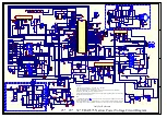
25"

29"

34" TDA9373 Narrow Power Voltage Circuit Diagram

O'

TO O


Only For Reference

BU2720DX

+17V

R741

100

ZD501

8.2V

C536
4700

EHT

G1 G2 G3

KB

KG

KR

XP205

R204
1.5K

R205 1.5K

R206
1.5K

1

2

3

4

5

6

XS201

CON6

1

2

3

4

XS202
CON5

S-Gnd

R208
1.5K

C203

1000pF/2KV

1

XP204

CON1

S-Gnd


V201

C2688/BF422

V202

BF422

V205

BF423

R?

R219

47

R220

10K

R221

10K

R222

10

R225

470

R217

15K

R218

470

D208

IN4148

C206
270P

V211

C2688/BF422

V210

BF422

V210

BF423

R237

47

R238

10K

R238
10K

R240

10

R241

470

R210

15K

R246

470

D216

IN4148

C208
270P

V231

C2688/BF422

V207

BF422

V208

BF423

R227

47

R228

10K

R229
10K

R236

10

R231

470

R232
15K

R235

470

D211
IN4148

C207
270P

R211 1K

R201
220K

C214

4.7u/500V

C214

0.1u/500V

R201 470

1

2

XP603
CON2

1

2

3

XS603

CON3

GND

Summary of Contents for CTM6845

Page 1: ...CHASSIS Brand Factory Model Serial no from To TEAC Syber CT M6845 3600001 49 3603120 49 TEAC Syber CT M6845 3603121 49 3606084 49 TEAC Syber CT M6845 3606085 49 3610062 49 TEAC Syber CT M6845 3800001 49 3802964 49 TEAC Syber CT M6845 3Y00001 49 3Y02340 49 TEAC Haier CT M6845 3Z00001 49 3Z02592 49 TEAC Haier CT M6845 4200001 49 4202340 49 JUN03 SERVCTM6845 ...

Page 2: ...UOC TDA9373 SERIES CT M6845 S S SE E ER R RV V VI I IC C CE E E M M MA A AN N NU U UA A AL L L COLOUR TELEVISION PUSH PUSH ...

Page 3: ...SECTION 1 ...

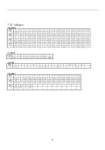
Page 4: ...ILIPS UOC functional difference between the various IC versions 4 3 Replacement of memory IC 7 4 Service adjustment 7 5 ICs functional description 9 6 Test point waveform 12 7 All ICs transistors voltages 13 8 Purity convergence adjustment 14 9 List of Parts 16 ...

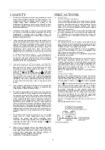
Page 5: ...not check high voltage by drawing an arc Use a high voltage meter or a high voltage probe with a VTVM Discharge the picture tube before attempting meter connection by connecting a clip lead to the ground frame and connecting the other end of the lead through a 10kΩ 2W resitor to the anode button 8 When service is required observe the original lead dress Extra precaution should be given to assure c...

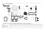
Page 6: ...ulator 4 5 6 5MHz With switch able centre frequency Audio switch TUNER SAW IF IN Y IN RF AGC V IN U IN CVBSINT CHROMA IFVO OUT CVBS Y IN SDA SCL AUDIO OUT IK RGB OUT V OUT H OUT S TRAP Vo V2i V1i Y Cr Cb ARi2 ARi1 ALi2 ALi1 S VHS 24C04 POWER UNIT 130V 24V 16V 8V 5V 3 3V CRT PCB V IN TDA8351 V OUT H IN H OUT H OUT DY 200V 15V 15V SCREEN FOCUS TDA93XX Vi1 OUT1 OUT1 Vi2 OUT2 OUT2 AN7522 CRT ALo ARo C...

Page 7: ... Horizontal and vertical zoom ROM size 32 64k 32 64k 32 64k 32 64k 64 128 64 128 64 128 64 128 64 128 64 128 64 128 64 128 16 64k 16 64k 16 64k 16 64k 16 64k 16 64k 16 64k 16 64k 16 64k 16 64k 32 55k 32 55k 32 55k 32 55k 32 55k User RAM size 1k 1k 1k 1k 2k 2k 2k 2k 2k 2k 2k 2k 1k 1k 1k 1k 1k 1k 1k 1k 1k 1k 2 25 2 25 2 25 2 25 2 25 Teletext 1 p 1p 1p 1p 10p 10p 10p 10p 10p 10p 10p 10p Closed captio...

Page 8: ... 6 ...

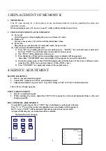
Page 9: ...red you need to input 828 4 Check the setting value of the SYSTEM default value of Table below If the value is different select items by CH CH keys and set value by VOL VOL keys 5 Press STANDBY key again and return to the normal screen 4 SERVICE ADJUSTMENT B1 POWER SUPPLY 1 Receive normal colour bar signal 2 Connect DC voltmeter to VD541 and isolated ground 3 Adjust potentiometer in power unit to ...

Page 10: ...llow more purple or more white b White balance adjustment 1 Select RD BD menu 2 Adjust RD BD to get colour temperature as x 281 y 311 c Sub Brightness adjustment Use stair case signal 1 Select SB menu 2 Adjust SB to get the darkest step being cutoff ICs Default Settings 1 TDA9381 1 0 EK cord NTDA9381 NG MI Items Variable Preset MI Items Variable Preset M0 AVL ON OFF ON M4 SUBCON 0 63 63 FSL ON OFF...

Page 11: ... 1 1 UOC VOL ON OFF Off CATHODE 0 15 15 M1 BAND 0 2 2 SC BRI 0 63 10 AV CFG 0 8 3 NTSC MX USA M6 LOGO ON OFF ON VIDEO OUT CVBS LOGO COLUR 0 7 0 PIN5 NTSC LOGO POSITION 0 11 0 PRO 0 3 0 LOGO CHAR SHIPMODE M2 VISION IF 38 9M SEARCH SPEED 0 3 0 DK ON OFF OFF BG ON OFF ON M7 AGC TOP 0 63 25 I ON OFF OFF AGC SPEED 0 3 2 M ON OFF OFF SIF PREFER BG M8 FREQUENCY 50HZ 60HZ AUTO SOUND ON OFF ON VSLOPE 0 63 ...

Page 12: ... EWD 20 Automatic volume leveling EAST WEST drive output VDRB 21 Vertical drive B output VDRA 22 Vertical drive A output IFIN1 23 IF input 1 IFIN2 24 IF input 2 IREF 25 Reference current input VSC 26 Vertical sawtooth capacitor TUNER AGC 27 Tuner AGC output AUDEEM SIFIN1 1 28 Audio deemphasis or SIF input DECSDEM SIFIN2 29 decoupling sound demodulator or SIF input 2 GND2 30 ground 2 for TV process...

Page 13: ...address 2BH TABLE 1 IC version FM PLL version QSS version East West Y N N Y N Y CMB1 CMB0 bits 00 01 10 11 00 01 10 11 00 01 10 11 00 01 10 11 AM bits 0 1 0 1 Pin 20 AVL EWD AVL EWD Pin 28 AUDEEM SIFIN1 Pin 29 DECSDEM SIFIN2 Pin 31 SNDPLL SIFAGC Pin 32 SNDIF 1 REFO 2 AVL SNDIF 1 REFO 2 AMOUT REFO 2 AMOUT REFO 2 Pin 35 AUDEXT AUDEXT QSSO AMOUT AUDEXT QSSO AMOUT Pin 44 AUDOUT Controlled AM or audio ...

Page 14: ...put OUT L 26 Left Output GND 8 Ground MAD 25 Not used GND LINOR 9 Line Output Right LINOL 24 Line Output Left LINIR 10 Line Input Right LINIL 23 Line Input Left CBR1 11 Bass Cap Right 1 CBL1 22 Bass Cap Left 1 CBR2 12 Bass Cap Right 2 CBL2 21 Bass Cap Left 2 Headphone R 13 Headphone R output Headphone L 20 Headphone L output CTR 14 Treble Cap Right CTL 19 Treble Cap Left MAINOR 15 Main Audio out R...

Page 15: ... 1 8 3 8 0 3 4 1 5 3 6 2 3 2 6 2 6 2 6 PIN 49 50 51 52 53 54 55 56 57 58 59 60 61 62 63 64 V 2 3 7 2 2 7 2 7 2 7 3 5 0 3 5 0 1 1 7 1 8 0 3 5 0 1 0 1 5 LA76040 PIN 1 2 3 4 5 6 7 V 0 7 15 12 15 0 3 15 9 0 07 AN 7522 PIN 1 2 3 4 5 6 7 8 9 10 11 12 V 12 7 0 7 3 3 1 4 0 1 4 0 7 0 7 TDA9859 PIN 1 2 3 4 5 6 7 8 9 10 11 12 13 14 V 4 0 0 4 0 8 0 4 0 8 0 4 0 0 4 0 4 0 4 0 4 0 4 0 4 0 PIN 15 16 17 18 19 20 2...

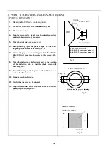
Page 16: ...o the center of the screen Fig 3 8 Move the deflection yoke forward and fix the position of the deflection yoke so that the whole screen will become green 9 Insert the wedge to the top side of the deflection yoke so that it will not move 10 Imput a crosshatch signal 11 Verify that the screen is horizontal 12 Input red and blue raster signals and make sure that purity is properly adjusted CRT WEDGE...

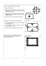
Page 17: ...t convergence DYNAMIC CONVERGENCE ADJUSTMENT 1 Move the deflection yoke up and down and overlap lines in the periphery Fig 2 2 Move the deflection yoke left to right and overlap the lines in the periphery Fig 3 3 Repeat 1 and 2 above and make the best convergence After adjustment fix the wedge at the original position Fasten the retainer screw of the deflection yoke Fix the 6 magnets with glue FRO...

Page 18: ... 8KΩ J T52 1 CARBON FILM RESISTOR RT13 1 6W 390Ω J T52 1 LED BT205 L 1 INRARED RECEIVER HS0038A IMPORTATION 1 WIRE WIRE 1 FRONT AV MODULE PRINTED CIRCUIT BOARD FRONT AV BOARD 1 AV SOCKET AV3 8 35 6AK 1 WIRE WIRE 1 FRONT FRAME MODULE BJK4076 Q 1 FRONT FRAME ASSEMBLY MTAA4086AA Q 1 FRONT FRAME ABS MTAA4098AA Q 1 LIGHT CONDUCTION COLUMN MTAH4057AA Q 1 BOLT SJ2825 87 ST3X8F 1 FUNCTION KEY MTAH4055AA Q...

Page 19: ...50 1 DEGUASSING COIL 1 GROUNDING WIRE 1 GAUCHE CONNECTING WIRE 1 BRACKET MODULE BXY4069 Q BRACKET MTAC4068AA Q 1 BOLT SJ2825 87 ST3X10F FBT TRANSFORMER TRESTLE MTAC4072AC Q 1 BOLT SJ2824 87 ST4X12F 2 POWER CABLE PRE WORKING MODULE POWER BUTTON CAP MTAB0014AA Q 1 POWER CABLE 1 POWER SWITCH 1 POWER TRANSMITTING WIRE 1 PACKING ARK MODULE 1 POWER CABLE PLASTIC BAG 1 WIRE 60mm 1 OPERATION INTRODUCTIONS...

Page 20: ...D 1 1 6W 15K R331 RDB154J NAATD 1 1 6W 150K R318 RDB181J NAATD 1 1 6W 180 R353 RDB182J NAATD 3 1 6W 1 8K R403 R405 R714 RDB183J NAATD 1 1 6W 18K R162 RDB220J NAATD 3 1 6W 22 R914 R924 R934 RDB221J NAATD 5 1 6W 220 R311 R442 R917 R927 R937 RDB222J NAATD 6 1 6W 2 2K R351 R371 R451 R540 R701AR804 RDB223J NAATD 2 1 6W 22K R384 R455 RDB242J NAATD 1 1 6W 2 4K R515 RDB272J NAATD 2 1 6W 2 7K R321 R512 RDB...

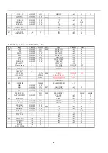
Page 21: ...RFD1R0J4ACCNF 1 1 2W 1 0 R473B RFER27J5ACDNF 3 1W 0 27 R555 R565 R566 RFER47J5ACDNF 3 1W 0 47 R165 R470 R472 RGDX246K 03NZ 1 1 2W 24M R519 RJB393F NAATD 1 1 6W 39K R411 RSE102J4ACCND 1 1W 1K R466 RSE1R5J4DCCND 1 1W 1 5 R406 RSE1R8J4DCCND 1 1W 1 8 R408 RSE220J5ACCND 1 1W 22 R300A RSF101J5ACDND 1 2W 100 R407 RSF103J5ACDND 5 2W 10K R467 R703 R915 R925 R935 RSF223J7ACDND 1 2W 22K R556 RSF271J7ACDND 2 ...

Page 22: ...CANP 8 16V47u C116 C171 C333 C352 C561 C723AC811 C823 CEC471MYACCNP 3 16V470u C525 C532 C801 CED101MYACBNP 5 25V100u C406 C471 C471AC474 C474A CED102M1ACHNP 1 25V1000u C522 CED222M2ACKNP 1 25V2200u C524 CED471M1ACENP 1 25V470u C161 CEE331M1ACFNP 1 35V330u C530 CEE470MYACCNP 1 35V47u C453 CEF1R0MYACANP 8 50V1u C153 C157 C163 C337 C804 C806 C813 C815 3 C825 C827 C862 CEF220MYACBNP 1 50V22u C703 CEF2...

Page 23: ...4148 VD171 VD461 VD462 VD482 VD511 VD544 VD561 VD562 4 VD734 VD911 VD921 VD931 DRBAV21 NJ 3 BAV21 VD912 VD922 VD932 DRGP15M ND 4 GP15M VD503 VD504 VD505 VD506 DRRGP10D TD 7 RGP10D VD401 VD470 VD471 VD510 VD512 VD522 VD525 DRRGP10J TD 3 RGP10J VD436 VD472 VD513 DRRGP15D ND 1 RGP15D VD543 DRRGP30D ND 1 RGP30D VD521 DRRGP30J ND 1 RGP30J VD524 DRTRU4C NZ 1 TRU4C VD452 DRTRU4DS NZ 1 TRU4DS VD451 DRTVR4...

Page 24: ...A 1 4S SOCKET XS161 GAGBD001 1 ICSOCKET1 78mm 64P XS1 GBAVL007 A 1 CRTSOCKET XS901 GBBA3 05 Y 1 AVSOCKET XS803 GBBB9 03 Y 1 AVSOCKET AV9 8 4 04 XS801 GBCH5001 Y 1 S SOCKET XS861 JW4451 J001 A 1 4P LINE 450mm D2 D2 XP402 JW5431 J132 A 1 5P LINE E3D 430mm XS903 TD 0042 0L 1 H DRIVERBCH 13 T450 TM 0097 0N 1 CON TRANS T501 BXATB066 X 1 TUNER 5V38 9 A101 M90X0003 91 1 INSULATED MAT18 13 D4 8 Z1 MB0X001...

Page 25: ...1 SFAC30010FE1H 3 SJ2836 87 M3 10 I SN503 SN161ASN161B SFAC30012FE1H 2 SJ2836 87 M3 12 I S N501 S V451 SKA 308R0FE H 2 GB845 78 ST3 8 S N505 S V432 SXN1A25 FF H 1 M2 5 NUT zz360 SXN1A30 FF H 5 M3 NUT N N501 N N503 N V451 NN161ANN161B SXW1A25 FE H 1 GB97 1 D2 5 FLATWASHIER ZN401 ...

Page 26: ...9 D882 P Gnd C847 100uF 16V Gnd C846 100uF 16V C845 100uF 16V C848 22uF 25V R837 2 2K Gnd Gnd Gnd Gnd Gnd 8V 5V 1 3 3V C835 470uF 25V Gnd 16V Gnd R808 120K R809 120K Gnd 1 2 3 4 5 6 7 8 9 10 11 12 13 14 15 16 0 0 0 1 1 1 N001 HEF4053 1 2 3 4 5 E 6 Vee 7 Vss 8 9 10 11 12 13 14 15 Vdd 16 0 1 2 3 0 1 2 3 2 TO 4 Decoder A0 A1 N002 HEF4052 C005 100nF C006 100nF C003 100nF C004 100nF R003 47K R002 47K R...

Page 27: ...UOC TDA9373 SERIES CT M6845 S S SE E ER R RV V VI I IC C CE E E M M MA A AN N NU U UA A AL L L COLOUR TELEVISION PUSH PUSH ...

Page 28: ...ILIPS UOC functional difference between the various IC versions 4 3 Replacement of memory IC 7 4 Service adjustment 7 5 ICs functional description 9 6 Test point waveform 12 7 All ICs transistors voltages 13 8 Purity convergence adjustment 14 9 List of Parts 16 ...

Page 29: ...not check high voltage by drawing an arc Use a high voltage meter or a high voltage probe with a VTVM Discharge the picture tube before attempting meter connection by connecting a clip lead to the ground frame and connecting the other end of the lead through a 10kΩ 2W resitor to the anode button 8 When service is required observe the original lead dress Extra precaution should be given to assure c...

Page 30: ...ulator 4 5 6 5MHz With switch able centre frequency Audio switch TUNER SAW IF IN Y IN RF AGC V IN U IN CVBSINT CHROMA IFVO OUT CVBS Y IN SDA SCL AUDIO OUT IK RGB OUT V OUT H OUT S TRAP Vo V2i V1i Y Cr Cb ARi2 ARi1 ALi2 ALi1 S VHS 24C04 POWER UNIT 130V 24V 16V 8V 5V 3 3V CRT PCB V IN TDA8351 V OUT H IN H OUT H OUT DY 200V 15V 15V SCREEN FOCUS TDA93XX Vi1 OUT1 OUT1 Vi2 OUT2 OUT2 AN7522 CRT ALo ARo C...

Page 31: ... Horizontal and vertical zoom ROM size 32 64k 32 64k 32 64k 32 64k 64 128 64 128 64 128 64 128 64 128 64 128 64 128 64 128 16 64k 16 64k 16 64k 16 64k 16 64k 16 64k 16 64k 16 64k 16 64k 16 64k 32 55k 32 55k 32 55k 32 55k 32 55k User RAM size 1k 1k 1k 1k 2k 2k 2k 2k 2k 2k 2k 2k 1k 1k 1k 1k 1k 1k 1k 1k 1k 1k 2 25 2 25 2 25 2 25 2 25 Teletext 1 p 1p 1p 1p 10p 10p 10p 10p 10p 10p 10p 10p Closed captio...

Page 32: ... 6 ...

Page 33: ...red you need to input 828 4 Check the setting value of the SYSTEM default value of Table below If the value is different select items by CH CH keys and set value by VOL VOL keys 5 Press STANDBY key again and return to the normal screen 4 SERVICE ADJUSTMENT B1 POWER SUPPLY 1 Receive normal colour bar signal 2 Connect DC voltmeter to VD541 and isolated ground 3 Adjust potentiometer in power unit to ...

Page 34: ...imes shows more yellow more purple or more white b White balance adjustment 1 Select RD BD menu 2 Adjust RD BD to get colour temperature as x 281 y 311 c Sub Brightness adjustment Use stair case signal 1 Select SB menu 2 Adjust SB to get the darkest step being cutoff ICs Default Settings 1 TDA9381 1 0 EK cord NTDA9381 NG MI Items Variable Preset MI Items Variable Preset M0 AVL ON OFF ON M4 SUBCON ...

Page 35: ...5 12 Volume mode 0 1 1 UOC VOL ON OFF Off CATHODE 0 15 15 M1 BAND 0 2 2 SC BRI 0 63 10 AV CFG 0 8 3 NTSC MX USA M6 LOGO ON OFF ON VIDEO OUT CVBS LOGO COLUR 0 7 0 PIN5 NTSC LOGO POSITION 0 11 0 PRO 0 3 0 LOGO CHAR SHIPMODE M2 VISION IF 38 9M SEARCH SPEED 0 3 0 DK ON OFF OFF BG ON OFF ON M7 AGC TOP 0 63 25 I ON OFF OFF AGC SPEED 0 3 2 M ON OFF OFF SIF PREFER BG M8 FREQUENCY 50HZ 60HZ AUTO SOUND ON O...

Page 36: ...rocessor DECBG 19 Band gap decoupling AVL EWD 20 Automatic volume leveling EAST WEST drive output VDRB 21 Vertical drive B output VDRA 22 Vertical drive A output IFIN1 23 IF input 1 IFIN2 24 IF input 2 IREF 25 Reference current input VSC 26 Vertical sawtooth capacitor TUNER AGC 27 Tuner AGC output AUDEEM SIFIN1 1 28 Audio deemphasis or SIF input DECSDEM SIFIN2 29 decoupling sound demodulator or SI...

Page 37: ...controlled via pin 49 or pin 50 the selection is made by means of the IVG bit in subaddress 2BH TABLE 1 IC version FM PLL version QSS version East West Y N N Y N Y CMB1 CMB0 bits 00 01 10 11 00 01 10 11 00 01 10 11 00 01 10 11 AM bits 0 1 0 1 Pin 20 AVL EWD AVL EWD Pin 28 AUDEEM SIFIN1 Pin 29 DECSDEM SIFIN2 Pin 31 SNDPLL SIFAGC Pin 32 SNDIF 1 REFO 2 AVL SNDIF 1 REFO 2 AMOUT REFO 2 AMOUT REFO 2 Pin...

Page 38: ...S2 27 Pseudo stereo Cap 2 OUT R 7 Right Output OUT L 26 Left Output GND 8 Ground MAD 25 Not used GND LINOR 9 Line Output Right LINOL 24 Line Output Left LINIR 10 Line Input Right LINIL 23 Line Input Left CBR1 11 Bass Cap Right 1 CBL1 22 Bass Cap Left 1 CBR2 12 Bass Cap Right 2 CBL2 21 Bass Cap Left 2 Headphone R 13 Headphone R output Headphone L 20 Headphone L output CTR 14 Treble Cap Right CTL 19...

Page 39: ... 1 8 3 8 0 3 4 1 5 3 6 2 3 2 6 2 6 2 6 PIN 49 50 51 52 53 54 55 56 57 58 59 60 61 62 63 64 V 2 3 7 2 2 7 2 7 2 7 3 5 0 3 5 0 1 1 7 1 8 0 3 5 0 1 0 1 5 LA76040 PIN 1 2 3 4 5 6 7 V 0 7 15 12 15 0 3 15 9 0 07 AN 7522 PIN 1 2 3 4 5 6 7 8 9 10 11 12 V 12 7 0 7 3 3 1 4 0 1 4 0 7 0 7 TDA9859 PIN 1 2 3 4 5 6 7 8 9 10 11 12 13 14 V 4 0 0 4 0 8 0 4 0 8 0 4 0 0 4 0 4 0 4 0 4 0 4 0 4 0 PIN 15 16 17 18 19 20 2...

Page 40: ...o the center of the screen Fig 3 8 Move the deflection yoke forward and fix the position of the deflection yoke so that the whole screen will become green 9 Insert the wedge to the top side of the deflection yoke so that it will not move 10 Imput a crosshatch signal 11 Verify that the screen is horizontal 12 Input red and blue raster signals and make sure that purity is properly adjusted CRT WEDGE...

Page 41: ...t convergence DYNAMIC CONVERGENCE ADJUSTMENT 1 Move the deflection yoke up and down and overlap lines in the periphery Fig 2 2 Move the deflection yoke left to right and overlap the lines in the periphery Fig 3 3 Repeat 1 and 2 above and make the best convergence After adjustment fix the wedge at the original position Fasten the retainer screw of the deflection yoke Fix the 6 magnets with glue FRO...

Page 42: ... 8KΩ J T52 1 CARBON FILM RESISTOR RT13 1 6W 390Ω J T52 1 LED BT205 L 1 INRARED RECEIVER HS0038A IMPORTATION 1 WIRE WIRE 1 FRONT AV MODULE PRINTED CIRCUIT BOARD FRONT AV BOARD 1 AV SOCKET AV3 8 35 6AK 1 WIRE WIRE 1 FRONT FRAME MODULE BJK4076 Q 1 FRONT FRAME ASSEMBLY MTAA4086AA Q 1 FRONT FRAME ABS MTAA4098AA Q 1 LIGHT CONDUCTION COLUMN MTAH4057AA Q 1 BOLT SJ2825 87 ST3X8F 1 FUNCTION KEY MTAH4055AA Q...

Page 43: ...50 1 DEGUASSING COIL 1 GROUNDING WIRE 1 GAUCHE CONNECTING WIRE 1 BRACKET MODULE BXY4069 Q BRACKET MTAC4068AA Q 1 BOLT SJ2825 87 ST3X10F FBT TRANSFORMER TRESTLE MTAC4072AC Q 1 BOLT SJ2824 87 ST4X12F 2 POWER CABLE PRE WORKING MODULE POWER BUTTON CAP MTAB0014AA Q 1 POWER CABLE 1 POWER SWITCH 1 POWER TRANSMITTING WIRE 1 PACKING ARK MODULE 1 POWER CABLE PLASTIC BAG 1 WIRE 60mm 1 OPERATION INTRODUCTIONS...

Page 44: ...D 1 1 6W 15K R331 RDB154J NAATD 1 1 6W 150K R318 RDB181J NAATD 1 1 6W 180 R353 RDB182J NAATD 3 1 6W 1 8K R403 R405 R714 RDB183J NAATD 1 1 6W 18K R162 RDB220J NAATD 3 1 6W 22 R914 R924 R934 RDB221J NAATD 5 1 6W 220 R311 R442 R917 R927 R937 RDB222J NAATD 6 1 6W 2 2K R351 R371 R451 R540 R701AR804 RDB223J NAATD 2 1 6W 22K R384 R455 RDB242J NAATD 1 1 6W 2 4K R515 RDB272J NAATD 2 1 6W 2 7K R321 R512 RDB...

Page 45: ...RFD1R0J4ACCNF 1 1 2W 1 0 R473B RFER27J5ACDNF 3 1W 0 27 R555 R565 R566 RFER47J5ACDNF 3 1W 0 47 R165 R470 R472 RGDX246K 03NZ 1 1 2W 24M R519 RJB393F NAATD 1 1 6W 39K R411 RSE102J4ACCND 1 1W 1K R466 RSE1R5J4DCCND 1 1W 1 5 R406 RSE1R8J4DCCND 1 1W 1 8 R408 RSE220J5ACCND 1 1W 22 R300A RSF101J5ACDND 1 2W 100 R407 RSF103J5ACDND 5 2W 10K R467 R703 R915 R925 R935 RSF223J7ACDND 1 2W 22K R556 RSF271J7ACDND 2 ...

Page 46: ...CANP 8 16V47u C116 C171 C333 C352 C561 C723AC811 C823 CEC471MYACCNP 3 16V470u C525 C532 C801 CED101MYACBNP 5 25V100u C406 C471 C471AC474 C474A CED102M1ACHNP 1 25V1000u C522 CED222M2ACKNP 1 25V2200u C524 CED471M1ACENP 1 25V470u C161 CEE331M1ACFNP 1 35V330u C530 CEE470MYACCNP 1 35V47u C453 CEF1R0MYACANP 8 50V1u C153 C157 C163 C337 C804 C806 C813 C815 3 C825 C827 C862 CEF220MYACBNP 1 50V22u C703 CEF2...

Page 47: ...4148 VD171 VD461 VD462 VD482 VD511 VD544 VD561 VD562 4 VD734 VD911 VD921 VD931 DRBAV21 NJ 3 BAV21 VD912 VD922 VD932 DRGP15M ND 4 GP15M VD503 VD504 VD505 VD506 DRRGP10D TD 7 RGP10D VD401 VD470 VD471 VD510 VD512 VD522 VD525 DRRGP10J TD 3 RGP10J VD436 VD472 VD513 DRRGP15D ND 1 RGP15D VD543 DRRGP30D ND 1 RGP30D VD521 DRRGP30J ND 1 RGP30J VD524 DRTRU4C NZ 1 TRU4C VD452 DRTRU4DS NZ 1 TRU4DS VD451 DRTVR4...

Page 48: ...A 1 4S SOCKET XS161 GAGBD001 1 ICSOCKET1 78mm 64P XS1 GBAVL007 A 1 CRTSOCKET XS901 GBBA3 05 Y 1 AVSOCKET XS803 GBBB9 03 Y 1 AVSOCKET AV9 8 4 04 XS801 GBCH5001 Y 1 S SOCKET XS861 JW4451 J001 A 1 4P LINE 450mm D2 D2 XP402 JW5431 J132 A 1 5P LINE E3D 430mm XS903 TD 0042 0L 1 H DRIVERBCH 13 T450 TM 0097 0N 1 CON TRANS T501 BXATB066 X 1 TUNER 5V38 9 A101 M90X0003 91 1 INSULATED MAT18 13 D4 8 Z1 MB0X001...

Page 49: ...1 SFAC30010FE1H 3 SJ2836 87 M3 10 I SN503 SN161ASN161B SFAC30012FE1H 2 SJ2836 87 M3 12 I S N501 S V451 SKA 308R0FE H 2 GB845 78 ST3 8 S N505 S V432 SXN1A25 FF H 1 M2 5 NUT zz360 SXN1A30 FF H 5 M3 NUT N N501 N N503 N V451 NN161ANN161B SXW1A25 FE H 1 GB97 1 D2 5 FLATWASHIER ZN401 ...

Page 50: ......

Page 51: ......

Page 52: ...SECTION 2 ...

Page 53: ...former in servicing 为了防止电的危险 不要去拆 To prevent electric shock don t remove cover 下机盖 必须委托够格的维修 Refer servicing to qualified service personnel 人员来进行维修 目录 电器规格 2 面板控制图 2 遥控器图 3 集成电路介绍 4 调试说明 10 更换部件一览表 附 常见故障的排除 14 线路图印制板图 附 Contents Electrical Specification 2 Panel Diagram 2 Remote Controller Diagram 3 ICs Introduction 4 Description of Adjustment 10 Replacement Part List 附 Common Faults Service 14 PC...

Page 54: ...SC Power consumption 14 65W 21 70W 25 110W 29 120W Power supply range AC 150V AC 260V Tuning range Full frequency band VHF UHF CATV Medium band 38 0MHz 38 9MHz or others Wireless input impedance 75Ω unbalanced AV input AV1 and AV2 AV output 1 channel Audible output 3W Loudspeaker impedance 8Ω Note It may differ depending on types Control panel diagram 6 7 TV AV MENU 5 4 P V 3 2 1 The adjusting but...

Page 55: ... 3 Rear view diagram AV IN sockets Antenna input and AV IN OUT sockets Remote controller diagram 6 5 4 CH TV AV PRESET SOUND MUTE VOL PICTURE PP SLEEP 7 FEATURE CLEAR 8 9 0 1 CALL 3 2 ...

Page 56: ... digital signal processing technique DSP Also inside the chip circuits such as bus controlled matrix switch 1H delay horizontal and comb filter are integrated All functions traditionally accomplished by cooperation with external circuits can all be performed inside the chip thus greatly increasing the signal processing ability of the chip realizing the self adapting adjustment for the control obje...

Page 57: ...B control as detailed in Fig 8 II Main composition and functions of main pins 1 Main composition This chassis is in standard single board structure in the overall layout the mature Sanyo power supply is used and the position numbers are arranged to international standard Its main IC s and their functions are as follows Position No 0 AV unit Position No 1 small signal unit Position No 2 video ampli...

Page 58: ...to S VHS signal input at port 0 switching to other signal source not used in this chassis Pin for control of the working status of comb filter 0 NTSC 1 PAL SECAM status It is used in 25 and 29 models for control of pillow distortion equalizing circuit in N system Pin local key Pin local key Pin not used Pin AV TV status output 1 TV 0 AV Pin sound system output Pin sound system output mainly as fol...

Page 59: ... machine Pin clock line SCL Pin data line SDA Pin stand by status stand by 0 working status 1 stand by status Pin 5V power supply 2 Memory block PCF8594 24C04 Pin 5V Pins Ground Pins Ground Pin Data line SDA Pin Data line SDA Pin Clock line SCL Pin Clock line SCL Pin NC not used Pin 5V power supply Pin 5V power supply 3 Color single chip small signal processing OM8838 TDA8842 The TDA8842 8838 pin ...

Page 60: ...Beam current limiter input V protection input 3 58 3 58 14 8 5 23 RIN For red primary color input to be inserted into picture 3 5 3 54 14 9 2 Red primary color for character 24 GIN For green primary color input to be inserted into picture 3 5 3 53 14 9 2 Green primary color for character 25 BIN For blue primary color input to be inserted into picture 3 5 3 52 14 9 2 Blue primary color for characte...

Page 61: ... drive A output 2 27 2 33 14 8 9 48 IFIN IF input 1 4 56 4 55 13 9 5 49 IFIN2 IF input 2 4 56 4 55 13 9 5 50 EHTO EHT over voltage protection input 0 28 0 28 1 2 1 2 51 VCS Vertical sawtooth input 3 75 3 75 14 9 2 52 Iref Reference current input 3 84 3 84 13 9 2 53 DECAGC AGC decoupling capacitor 4 43 1 18 14 9 2 54 AGCOUT Tuner AGC output 1 90 4 24 5 5 5 5 55 AUDEEM Audio deemphasis 2 88 2 86 14 ...

Page 62: ...al output Pin Ground Pin Pump power supply 45V negative pulse Pin Vertical protection Pin Vertical feedback The pins functions of 8356 and 8351 are all the same only 8356 I 2A 8351 I 3A 6 Video amplification TDA6107Q TDA6108JF Pin No Function Pins R G and B input Pin Ground Pin Dark balance testing output Pin Working voltage 180V Pins R G and B output 6107 and 6108 pins are all the same 6107 has a...

Page 63: ...ing left and right positions of characters OSDORGV for adjusting up and down positions of characters OSDPLL set value 120 Note The characters positions for PAL system signal and NTSC system signal should be adjusted separately Press the Maintenance key twice to enter the second menu under factory status which gives the following display Remarks V SLOPE Vertical semi blanking adjustment specificall...

Page 64: ...ustment G brightness balance green gun adjustment B brightness balance blue gun adjustment C set value is adjustable between 1 6 is determined by CRT driving voltage and has been set as a fixed value when leaving the factory Press the Maintenance key five times to enter the fifth menu under factory status which gives the following display Remarks AGC TAK set value 3 VOLUME CON set value 35 45 This...

Page 65: ...ngle audio channel Press the Maintenance key eight times to enter the level eighth menu which gives the following display Remarks PAL 4 43 set value 1 NTSC 3 58 set value 1 NTSC 4 43 set value 1 SECAM set value 0 it is a set value for 8842 DK set value 0 1 for full system BG set value 0 1 for full system I set value 0 1 for full system M set value 0 1 for full system OPTION 1 PAL 4 43 1 NTSC 3 58 ...

Page 66: ...ependent electron guns to control three independent electron beams which are converged to hit the respective fluorescent materials They should show white when mixed but the luminous efficiency of the fluorescent materials cannot be the same due to the characteristics of elements in the three amplifiers and the electron emitting ability of the electron gun cathodes Therefore balance adjustment must...

Page 67: ...ts of the TDA8842 8838 then the cathode current electron beam current of the three guns of the CRT is checked and compared with the same standard to correct the output of R G and B by negative feedback mode according to their difference until the cathode current of the three guns are equalized showing white The entire adjustment is automatically performed under the control by the IIC bus With Figs...

Page 68: ...it will damage at the same time 2 Circuit analysis and maintenance for three no s fault The fault of no picture no sound and no power supply indication hereinafter referred to as three no s fault is a fault with high probability of occurrence in TDA8842 OM8838 series chassis The following faults can be repaired using the methods described below Indicator is not ON The fault is mainly in the power ...

Page 69: ...e other elements Therefore for the repair of this three no s fault in the chassis it is permitted to cut off the power supply protection system of the microcomputer CPU then to monitor the change in voltage at various critical points quickly after forced on so as to analyze the location of the fault The soft start means in each turning on there is a transition period from start to normal without e...

Page 70: ...icator is ON Power supply section N807 damaged and V809 damaged Three no s the indicator is not ON Power supply section N805 damaged Top retrace horizontal Vertical section D406 damaged and R307 damaged Top retrace horizontal Vertical section N301 damaged and R307 damaged Three no s the indicator is ON Horizontal section V401 damaged Horizontal bright horizontal Vertical section R306 damaged and D...

Page 71: ...TING PIN R 1 G0611160 RADIATING PIN SOUND 1 G0611240 RADIATING PIN POWER 1 G3600010 ISINGLASS PARCEL 1 G7310000 FUSE CILP 2 G7310050 REED 1 G8203227 PCB BOARD MAIN 1 G8203850 PCB BOARD CRT 1 G8205381 PCB BOARD KEY 1 G8205390 PCB BOARD AV 1 G8440130 ISINGLASS PARCEL 1 G8500000 WIRE COVER 1 06000000 OUTSOURCING 0 J2160003 COMPLETE SCREW M3 12Ⅰ 1 J2160003 COMPLETE SCREW M3 12Ⅰ 2 J2160003 COMPLETE SCR...

Page 72: ...00000 RT13 1 6W 82Ω 5 1 R007 18200000 RT13 1 6W 82Ω 5 1 R008 18200000 RT13 1 6W 82Ω 5 1 R009 18200000 RT13 1 6W 82Ω 5 1 R108 6 11001000 RT13 1 6W 100Ω 5 1 R301 11001000 RT13 1 6W 100Ω 5 1 R305 11001000 RT13 1 6W 100Ω 5 1 R521 11001000 RT13 1 6W 100Ω 5 1 R745 11001000 RT13 1 6W 100Ω 5 1 R757 11001000 RT13 1 6W 100Ω 5 1 R766 11001000 RT13 1 6W 100Ω 5 1 R902 11001000 RT13 1 6W 100Ω 5 1 R905 11001000 ...

Page 73: ...29 16801000 RT13 1 6W 680Ω 5 1 R590 3 11002000 RT13 1 6W 1KΩ 5 1 R418 11002000 RT13 1 6W 1KΩ 5 1 R467 11002000 RT13 1 6W 1KΩ 5 1 R479 11002000 RT13 1 6W 1KΩ 5 1 R503 11002000 RT13 1 6W 1KΩ 5 1 R505 11002000 RT13 1 6W 1KΩ 5 1 R512 11002000 RT13 1 6W 1KΩ 5 1 R525 11002000 RT13 1 6W 1KΩ 5 1 R533 11002000 RT13 1 6W 1KΩ 5 1 R535 11002000 RT13 1 6W 1KΩ 5 1 R714 11002000 RT13 1 6W 1KΩ 5 1 R746 11 1120200...

Page 74: ...02000 RT13 1 6W 3 3KΩ 5 1 R759 13302000 RT13 1 6W 3 3KΩ 5 1 R700 4 13902000 RT13 1 6W 3 9KΩ 5 1 R401 13902000 RT13 1 6W 3 9KΩ 5 1 R430 13902000 RT13 1 6W 3 9KΩ 5 1 R480 3 14702000 RT13 1 6W 4 7KΩ 5 1 R105 14702000 RT13 1 6W 4 7KΩ 5 1 R312 14702000 RT13 1 6W 4 7KΩ 5 1 R626 14702000 RT13 1 6W 4 7KΩ 5 1 R635 14702000 RT13 1 6W 4 7KΩ 5 1 R756 14702000 RT13 1 6W 4 7KΩ 5 1 W1100 6 15102000 RT13 1 6W 5 1...

Page 75: ...01 11003000 RT13 1 6W 10KΩ 5 1 R705 11003000 RT13 1 6W 10KΩ 5 1 R727 11003000 RT13 1 6W 10KΩ 5 1 R728 11003000 RT13 1 6W 10KΩ 5 1 R740 11003000 RT13 1 6W 10KΩ 5 1 R771 11003000 RT13 1 6W 10KΩ 5 1 R775 11003000 RT13 1 6W 10KΩ 5 1 R777 11003000 RT13 1 6W 10KΩ 5 1 R778 11003000 RT13 1 6W 10KΩ 5 1 R830 11003000 RT13 1 6W 10KΩ 5 1 R901 11003000 RT13 1 6W 10KΩ 5 1 R722 22 11203000 RT13 1 6W 12KΩ 5 1 R11...

Page 76: ...4703000 RT13 1 6W 47KΩ 5 1 R608 14703000 RT13 1 6W 47KΩ 5 1 R612 14703000 RT13 1 6W 47KΩ 5 1 R627 14703000 RT13 1 6W 47KΩ 5 1 R637 14703000 RT13 1 6W 47KΩ 5 1 R785 14703000 RT13 1 6W 47KΩ 5 1 W907 9 15603000 RT13 1 6W 56KΩ 5 1 R451 16803000 RT13 1 6W 68KΩ 5 1 R903 16803000 RT13 1 6W 68KΩ 5 1 R904 2 11004000 RT13 1 6W 100KΩ 5 1 R475 11004000 RT13 1 6W 100KΩ 5 1 R625 11004000 RT13 1 6W 100KΩ 5 1 R63...

Page 77: ...1 RT14 1 4W 330Ω 5 1 R221 13301001 RT14 1 4W 330Ω 5 1 R225 13301001 RT14 1 4W 330Ω 5 1 R229 13301001 RT14 1 4W 330Ω 5 1 R231 13301001 RT14 1 4W 330Ω 5 1 R239 13301001 RT14 1 4W 330Ω 5 1 R241 6 11002001 RT14 1 4W 1KΩ 5 1 R408 15101001 RT14 1 4W 510Ω 5 1 R807 12702001 RT14 1 4W 2 7KΩ 5 1 R816 12702001 RT14 1 4W 2 7KΩ 5 1 R829 2 13302001 RT14 1 4W 3 3KΩ 5 1 R425 13302001 RT14 1 4W 3 3KΩ 5 1 R806 2 14...

Page 78: ...Ω 5 1 R801 12204002 RT15 1 2W 220KΩ 5 1 2 11800451 MZ73 18RM270 1 RT801 14708207 RF10 1W 0 47Ω 10 1 R209 14708207 RF10 1W 0 47Ω 10 1 R490 2 12207207 RF10 1W 2 2Ω 10 1 R306 11007208 RF10 2W 1Ω 10 1 R427 11502303 RI40 1 2W 1 5KΩ 10 1 R206 11502303 RI40 1 2W 1 5KΩ 10 1 R207 11502303 RI40 1 2W 1 5KΩ 10 1 R208 3 11206301 RS11 1 2W 12MΩ 10 1 R819 11206301 RS11 1 2W 12MΩ 10 1 R820 2 11007101 RY16 1W 1Ω 5...

Page 79: ...13903603 RJ24 1 4W 39KΩ 1 1 R530 13002603 RJ24 1 4W 3KΩ 1 1 R302 11004601 RJ15 1 2W 100KΩ 2 1 R822 11807506 RX27 3 5 5W 1 8Ω 10 1 R802 15607502 RX27 6W 5 6Ω 10 卧式 1 R412 11800401 RGCW5 5W 18Ω 10 1 R812 12002704 WI06 2E 2KΩ 20 1 RP801 11003702 WI06 2E 10KΩ 20 1 RP450 15003702 WI06 2E 50KΩ 20 1 RP451 20000000 CAPACITOR 0 21500002 CC1 06 63V 15pF 5 CH 1 C729 24700002 CC1 06 63V 47pF 5 CH 1 C507 24700...

Page 80: ...000pF 10 2B4 1 C620 21002335 CT1 06 63V 1000pF 10 2B4 1 C950 10 24702315 CT1 12 63V 4700pF 10 2B4 1 C117 24702315 CT1 12 63V 4700pF 10 2B4 1 C908 24702315 CT1 12 63V 4700pF 10 2B4 1 C918 3 21003339 CT1 08 63V 0 01μF 10 2F4 1 C109 21003339 CT1 08 63V 0 01μF 10 2F4 1 C110 21003339 CT1 08 63V 0 01μF 10 2F4 1 C111 21003339 CT1 08 63V 0 01μF 10 2F4 1 C112 21003339 CT1 08 63V 0 01μF 10 2F4 1 C116 210033...

Page 81: ...KV 1000pF 10 2B4 1 C806 21002424 CT81 08 1KV 1000pF 10 2B4 1 C807 21002424 CT81 08 1KV 1000pF 10 2B4 1 C808 21002424 CT81 08 1KV 1000pF 10 2B4 1 C809 4 21002442 CT81 10 2KV 1000pF 10 2B4 1 C205 21502401 CT81 12 2KV 1500pF 10 2B4 1 C816 23303508 CBB21 400V 0 033μF 10 1 C413 23904508 CBB21 400V 0 39μF 5 1 C418 22204516 CBB62 250VAC 0 22μF 5 1 C801 22204516 CBB62 250VAC 0 22μF 5 1 C802 2 28202514 CBB...

Page 82: ...21004206 CL11 63V 0 1μF 5 1 C910 9 21004216 CL21X 50V 0 1μF 10 1 C102 21004216 CL21X 50V 0 1μF 10 1 C455 21004216 CL21X 50V 0 1μF 10 1 C457 21004216 CL21X 50V 0 1μF 10 1 C730 21004216 CL21X 50V 0 1μF 10 1 C731 5 22204216 CL21X 50V 0 22μF 10 1 C459 22204216 CL21X 50V 0 22μF 10 1 2 24704217 CL21X 63V 0 47μF 10 1 C626 22204219 CL21X 100V 0 22μF 10 1 C309 24701708 CT7 12 400VAC 470pF 10 1 C820 2100270...

Page 83: ...D110 16V 100μF 20 1 C452 21007104 CD110 16V 100μF 20 1 C512 21007104 CD110 16V 100μF 20 1 C521 21007104 CD110 16V 100μF 20 1 C534 21007104 CD110 16V 100μF 20 1 C732 21007104 CD110 16V 100μF 20 1 C838 21007104 CD110 16V 100μF 20 1 C912 8 24705105 CD110 25V 4 7μF 20 1 C628 24705105 CD110 25V 4 7μF 20 1 C633 2 21006105 CD110 25V 10μF 20 1 C001 21006105 CD110 25V 10μF 20 1 C616 21006105 CD110 25V 10μF...

Page 84: ...0 50V 1μF 20 1 C909 6 21006107 CD110 50V 10μF 20 1 C451 21006107 CD110 50V 10μF 20 1 C703 2 22206107 CD110 50V 22μF 20 1 C306 21007107 CD110 50V 100μF 20 1 C305 21007109 CD110 63V 100μF 20 1 C416 21005133 CD114 16V 1μF 20 1 C533 21005119 CD288 160V 1μF 20 1 C427 24705120 CD288 250V 4 7μF 20 1 C214 22206120 CD288 250V 22μF 20 1 C415 24707119 CD288 160V 470μF 20 1 C822 23307123 CD293 400V 330μF 20 1...

Page 85: ...0000 SEMICONDUCTOR 0 41010004 FW314055 FW314034S 1 D701 41020001 1N4148 1 D208 41020001 1N4148 1 D211 41020001 1N4148 1 D216 41020001 1N4148 1 D301 41020001 1N4148 1 D408 41020001 1N4148 1 D410 41020001 1N4148 1 D411 41020001 1N4148 1 D450 41020001 1N4148 1 D601 41020001 1N4148 1 D807 41020001 1N4148 1 D809 41020001 1N4148 1 D810 41020001 1N4148 1 D901 41020001 1N4148 1 D905 41020001 1N4148 1 D906...

Page 86: ...030030 GP15M TVR4N 1 D802 41030030 GP15M TVR4N 1 D805 41030030 GP15M TVR4N 1 D806 4 41030011 1N4004 1 D808 41030029 3JH61 1 D811 41030016 BYV99C 2A 1 D812 41030016 BYV99C 2A 1 D815 2 41030009 FR305 1 D816 41030022 BYV95B 1 D405 41030023 BYD33G 1 D406 41030020 BYD33J 1 D407 41030031 BY228 1 D412 41030021 BYW95C 1 D415 42000011 2SA1015Y 1 V801 42000072 2SC4237 1 V802 42000019 2SC3807 CTV YA 1 V805 4...

Page 87: ...48 B 1 V902 42000032 BC548 B 1 V903 19 42000033 BC558 B 1 V450 42000033 BC558 B 1 V456 42000033 BC558 B 1 V506 42000033 BC558 B 1 V601 4 42000016 2SC2688K 1 V201 42000016 2SC2688K 1 V206 42000016 2SC2688K 1 V211 3 42000062 BF420 BF422 1 V202 42000062 BF420 BF422 1 V207 42000062 BF420 BF422 1 V209 3 42000063 BF421 BF423 1 V205 42000063 BF421 BF423 1 V208 42000063 BF421 BF423 1 V210 3 42000002 2SC18...

Page 88: ...4000002 LTV817B C P817B 1 N801 51100001 RG T 3 15A 250V 1 F801 52010012 ENV59D68F1E 1 U101 52060001 HS0038 1 CP701 51070004 LT 5 5M 1 Z502 51080004 XT 5 5M 1 Z508 51040007 JA18A 12 0MHz 1 X701 51040003 JA18B 4 43MHz 1 X901 51040004 JA25C 3 58MHz 1 X902 51050010 K2951A 1 Z101 53010003 GZS10 2 10C3 1 X200 52020002 YDT813 8W 16Ω 2 52070027 CD0329A 1 53030016 SW 2 1 X002 53020042 AV3 8 4 307 1 XS1103 ...

Page 89: ...G G1 E5690111 TERMINAL PLUG TJC3 4Y 420 1 XS202 E5690150 TERMINAL PLUG TJC2 5Y 420 1 XS402 E5690180 TERMINAL PLUG TJC3 4Y 700 1 XS602 E5690210 TERMINAL PLUG TJC1 2Y 200 1 XS803 E5690410 TERMINAL PLUG TJC3 3Y 450 1 XS1100 E5691250 TERMINAL PLUG TJC3 3Y 250 1 XS702 E5691260 TERMINAL PLUG TJC3 5Y 250 1 XS701 E5691290 TERMINAL PLUG TJC3 5Y 420 1 XS201 54020004 KFC A06 A 1 5mm 1 SW701 54020004 KFC A06 ...

Page 90: ......

Page 91: ......

Page 92: ......

Reviews: