


2
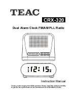
DESCRIPTION OF THE UNIT
OPERATING INSTRUCTIONS
Connecting to the power supply
Insert the AC adapter into a 230V AC ~ 50Hz mains outlet and the other end of
the cord into the DC 6V jack on the back of the unit.
Installing the clock back up batteries
The clock time can be maintained during a power failure by 2 x AA/ LR06
batteries (not supplied). However, the time may go forward or back slightly and
may need resetting.
Inserting the batteries
1. Open the battery compartment at the back of the unit by pressing on the catch
and removing the cover.
2. Insert 2 x AA/ LR06 batteries (preferably alkaline batteries) into the battery
compartment, following the polarity as shown on the diagram inside the
compartment.
3. Replace the battery compartment cover.
1. Speaker
2. SNOOZE/SLEEP button
3. CLK/MEM (Clock/Memory) button
4.
(Standby)/SOURCE button
5. AL1/AL2 (Alarm), VOL (Volume)
buttons
6. HOUR/MIN (Minute), <TUNING>
buttons
7. DC 6V jack
8. PM indicator
9. AL1 (Alarm) BUZZ/RADIO
indicator
10. LED display
11. Clock back-up battery compartment
12. AL2 (Alarm) BUZZ/RADIO
indicator
13. FM antenna wire
BUZZ
RADIO
Al1
BUZZ
RADIO
Al2
pm
1
2
3 4
5
6
7
8
9
10 11
13
12