background image

24

24

4 Adjustments

4.2.4  Adjusting the Transfer Ribbon Feed Path

You can adjust the transfer ribbon feed path by changing the head contact pressure and adjusting the transfer ribbon 

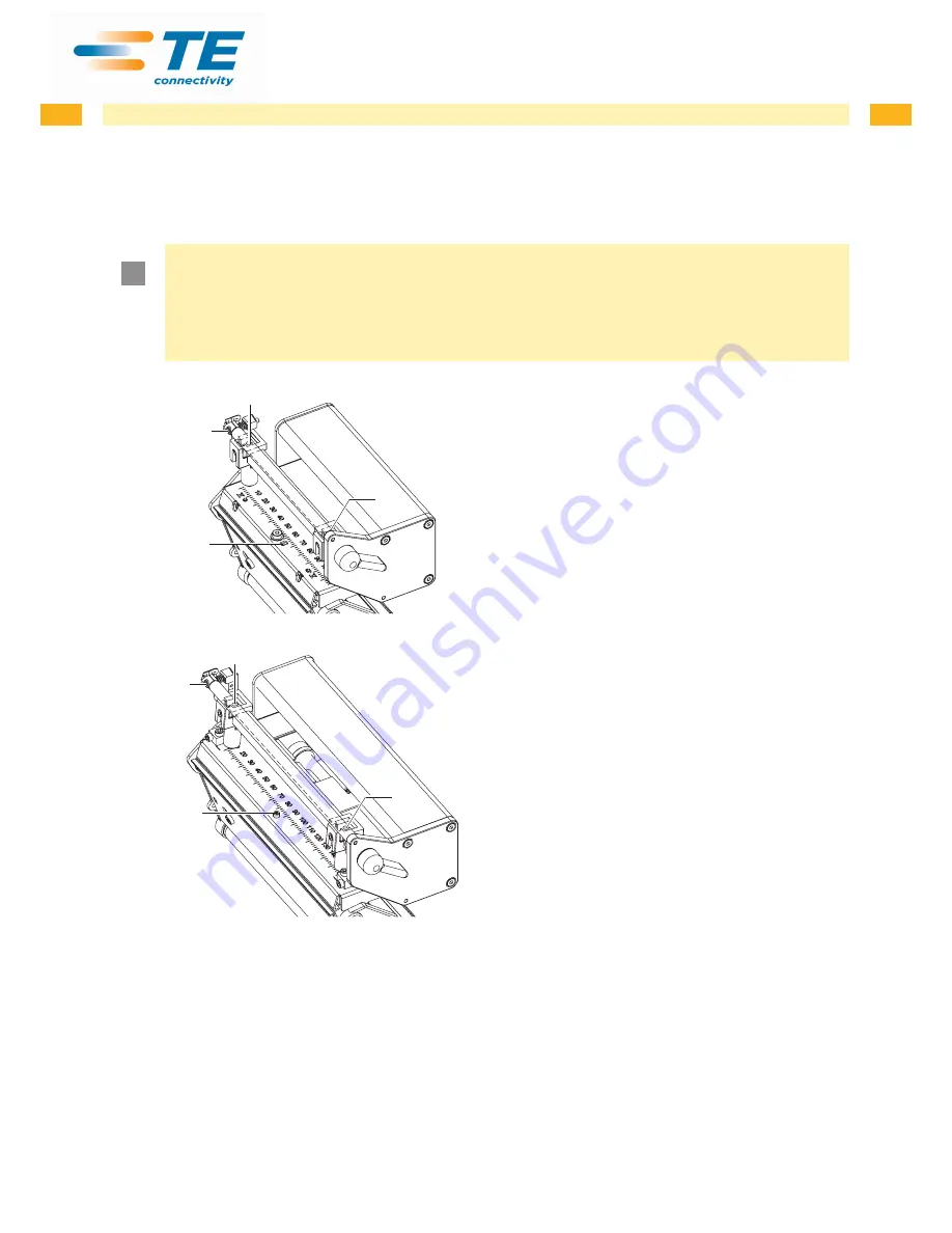
deflection. Increasing the head contact pressure with the screws (3a) and (3b) shifts the ribbon feed path in the 

corresponding direction. The skew of the transfer ribbon deflection is used to suppress wrinkles in the transfer ribbon 

feed path. Wrinkles which cannot be remedied with the skew of the transfer ribbon deflection can be suppressed by 

bowing the printhead.

!

Attention!

The printhead assembly can be damaged when bowing the printhead.
Turning the adjustment screw (1) too hard can cause damage to the printhead assembly.


X

As soon as you perceive clear resistance when turning the adjustment screw (1), you may only continue 

turning the screw in very small increments, but no more than one eighth of a turn.


X

Only turn the adjustment screw (1) as far as is absolutely necessary.

2

1

3a

3b

3a

2

1

3b

1.  Check the transfer ribbon feed path. 

The wound up ribbon should be the same distance 

from the disk of the winder as the supply roll is from 

the disk of the supply hub.

2.  If the ribbon runs inward or outward, turn the corre-

sponding screw (3a) or (3b) clockwise in small 

increments.

3.  Wait until the ribbon feed path has stabilized after 

each step of the adjustment.

4.  Check the ribbon feed path for wrinkles.
5.  If wrinkles arise on the inside, turn the screw (2) 

counterclockwise.

6.  If wrinkles arise on the outside, turn the screw (2) 

clockwise.

7.  If the wrinkles cannot be remedied (e.g. wrinkles in 

the center), turn the adjustment screw (1) clockwise 

with extreme care

 using an Allen key (1.5 mm) and 

observe the ribbon feed path. 

When the adjustment screw (1) is tightened, the 

printhead is bent downward slightly in the center. It is 

possible that a slight lightening at the edge areas of 

the print image could occur here.

8.  If bowing is not necessary, turn the screw (2) 

clockwise until the screw is just barely clamping.

9.  When the transfer ribbon feed path is set, continue 

with the final test.

Fig. 20 

Adjusting the transfer ribbon feed path

4.2.5  Final Test


X

Reset the 

Heat level

 to +5 in the printer configuration 


X

Recheck the setting with the test function 

Test grid

  or a similar print pattern.

When using standard media, the test printout must show lines with sharp contours and black areas without any parts 

missing.

Summary of Contents for TE3112

Page 1: ...PB Service Manual TE3124 TE3112 Thermal Transfer Printer...

Page 2: ...any 49 0 173 3169004 Email ident tech support te com Ireland Toll Free 800 557 810 Phone is monitored in the afternoon local time Email ident tech support te com Rest of Europe http www te com help Em...

Page 3: ...acing Label Sensor 14 3 7 Replacing the PCB CPU 15 3 8 Replacing the Power Supply Unit 16 4 Adjustments 17 4 1 Measuring and Adjusting the Winding Torques 17 4 1 1 Measuring the Winding Torques 17 4 1...

Page 4: ...device X X Do not wear clothing with metal parts X X Do not wear jewelry X X Do not wear spectacles with metal frames Warning Items of clothing drawn into the device by moving parts can lead to injur...

Page 5: ...ing circuits in the device Test the zero potential of the device parts Check the working area for possible sources of danger such as wet floors defective extension cables defective protective conducto...

Page 6: ...the device cleaning the printhead cleaning the print roller cleaning the label sensor Danger Risk of death via electric shock X X Before opening the housing cover disconnect the device from the mains...

Page 7: ...2 so deep as possible into the guide profile toward the chassis 7 Slide out the label sensor assembly 2 toward the back side cover 8 Clean label sensor and sensor units 2 with brush or cotton swab soa...

Page 8: ...tion The plastic cover can be damaged via careless handling X X Do not use force X X Do not twist the plastic cover when removing it or pressing it on Fig 3 Removing and installing the plastic cover R...

Page 9: ...g line 6 Pins 7 Printhead Fig 4 Structure of the printhead Attention The printhead 7 is adjusted on a head plate 1 and precisely aligned at the factory Do not loosen the screws 4 under any circumstanc...

Page 10: ...d from the printhead mounting bracket 9 if necessary 7 Loosen both plug connections 2 3 on the printhead and set printhead down on a clean soft surface Installing the printhead 1 Attach plug connectio...

Page 11: ...Fig 6 Slipping clutches Danger Risk of death via electric shock X X Before opening the housing cover disconnect the device from the mains supply and wait at lease one minute until the power supply uni...

Page 12: ...l sensor toward the cover side as far as possible and install the rear cover of the printer Installing the brake on the transfer ribbon supply hub 12 7 11 9 4 10 4 Snap ring 7 Winder axis 9 Brake 10 L...

Page 13: ...nto the tab 4 toward the rear cover until it stops 5 Unplug the cable 2 from the plug on the rear end of the label sensor 1 6 Unscrew the screws 5 with an Allen key and remove the side plate 7 7 Pull...

Page 14: ...sor 2 so deep as possible into the guide profile toward the chassis 6 Slide out the label sensor assembly 2 toward the back side cover Installing the label sensor 1 Push label sensor back toward the p...

Page 15: ...Remove the PCB CPU Fig 11 Removing the PCB CPU 4 5 6 7 8 9 10 Fig 12 Used connectors on the PCB CPU 4 Control panel 5 Peripheral port 6 Sensors 7 Printhead signals 8 Printhead power supply 9 Power su...

Page 16: ...t input 3 6 Unplug the plug at the power supply unit output 1 7 Remove the two screws on the back of the printer 7 8 Hold the power supply unit firmly at the metal bracket 4 and remove the two screws...

Page 17: ...ons The measured clockwise torque is the sum of the coupling torque and the torque of the brake Only the torque of the brake is measured when the winding axis is rotating counter clockwise For this re...

Page 18: ...y unit has discharged 1 Unplug the printer from the electrical outlet 2 Remove the rear cover 3 Remove the transfer ribbon from the printer 4 Attach the test collar 3 to the winder 4 5 Turn the knurle...

Page 19: ...t the device from the mains supply and wait at lease one minute until the power supply unit has discharged 3 1 2 4 1 Unplug the printer from the electrical outlet 2 Remove the rear cover 3 Remove the...

Page 20: ...ly unit has discharged 2 1 1 Unplug the printer from the electrical outlet 2 Remove the rear cover 3 Press the knurled ring 1 of the slipping clutch toward the housing wall The lock 2 of the knurled r...

Page 21: ...inting mechanism comprises the following procedures in the order specified 1 Prepare the label printer for adjustment 4 2 1 on page 21 2 Adjust the position of the printhead 4 2 2 on page 22 3 Adjust...

Page 22: ...ment 1 Check the alignment of the printhead in the adjustment windows 1 2 If the printhead is not aligned properly loosen the screw 3 about one quarter turn 3 If the printhead is not aligned properly...

Page 23: ...barely recognizable Under these conditions inaccuracies become clearly visible during adjustment 3 Create print samples with the test function Test grid or a similar print pattern 4 Adjust the adjustm...

Page 24: ...der as the supply roll is from the disk of the supply hub 2 If the ribbon runs inward or outward turn the corre sponding screw 3a or 3b clockwise in small increments 3 Wait until the ribbon feed path...

Page 25: ...rub against the label sensor during printing which would damage the belt X X Tension the toothed belt in such a way that it cannot rub against the label sensor 3 4 2 1 1 Unplug the printer from the el...

Page 26: ...the power supply unit has discharged 1 2 3 2 3 1 Unplug the printer from the electrical outlet 2 Remove the rear cover 3 Lock printhead 4 Slightly loosen the fixing screws 3 of the head switch 2 5 Mov...

Page 27: ...point The power supply unit may be defective Replace the power supply unit No voltage at one measurement point The PCB CPU may be defective Replace the PCB CPU Replace LCD Display cpl Replace PCB Nav...

Page 28: ...tage too low Replace the power supply unit Voltage is correct Replace the PCB CPU 24 V 24 V too low Check voltage at measurement point 24V Fig 25 on page 31 Voltage too low Replace the power supply un...

Page 29: ...6 Block Diagram Printer Type Nr 1 Nr 2 Nr 3 Nr 4 Nr 5 Nr 6 TE3112 TE3124 300dpi 5954072 5954067 5954066 5946208 5954099 5958670 600dpi 5954077 5954067 5954066 5946208 5954099 5958670 Fig 23 Block dia...

Page 30: ...30 30 7 Layout Diagram PCB CPU Fig 24 Layout diagram PCB CPU components side...

Page 31: ...30 31 7 Layout Diagram PCB CPU Fig 25 Layout diagram PCB CPU soldering side...

Page 32: ...re faults 28 I Internal rewinder winding torque 19 L Label sensor cleaning 6 7 replacement 14 Layout diagram PCB CPU 31 P Printhead replacing 9 Procedure in case of accidents 5 Protective devices 4 Pu...

Reviews: