


NOTE
i
408-8881
2 of 3
Rev A
2. Insert the indenter into the stationary jaw so that
the chamfer faces outward.
3. Place two retaining pins through the tool frame
and indenter.
4. Thread, but do not tighten, a die retention screw
through the center hole in the jaw so that the die is
held in place.
5. Insert the anvil into the movable jaw so that the
chamfer faces outward.
6. Place two retaining pins through the tool frame
and anvil.
7. Thread, but do not tighten, a die retention screw
through the center hole in the jaw so that the die is
held in place.
8. Slowly close the tool handles, allowing the dies to
mate and align. Continue closing the handles until
the ratchet makes the fifth “click”, then tighten both
die retention screws.
The ratchet has detents with audible “clicks” as the
handles are closed. The ratchet releases on the
sixth “click”.
4. CRIMPING PROCEDURE
NOTE
i
This tool is provided with a crimp adjust feature.
Initially, the crimp height should be verified as
specified in Figure 3. Refer to Section 5, CRIMP
HEIGHT INSPECTION, and Section 6, CRIMP
HEIGHT ADJUSTMENT, to verify crimp height
before using the tool to crimp desired contacts and
wire sizes.
Refer to the table in Figure 1 and select wire of the
appropriate size and insulation diameter. Strip the wire
to the length specified in Figure 1, taking care not to
nick or cut wire strands. Select an applicable contact
and identify an appropriate crimp section according to
the wire size markings on the tool.
NOTE
i
1. Squeeze the tool handle together until the ratchet
releases. Allow the tool handles to open FULLY.
Keep wire pins in strip form during
crimping procedure.
!
CAUTION
2. Holding the wire pins by the strip, place the wire
pin on the end of the strip in the appropriate crimp
section.
3. Position the wire pin so that it is centered in the
crimp section and squeeze the tool handles
together until the ratchet engages sufficiently to
hold the wire pin in place without deforming it.
Make sure that both sides of the wire barrel are
started evenly into the crimping section. Do NOT
attempt to crimp an improperly positioned contact.
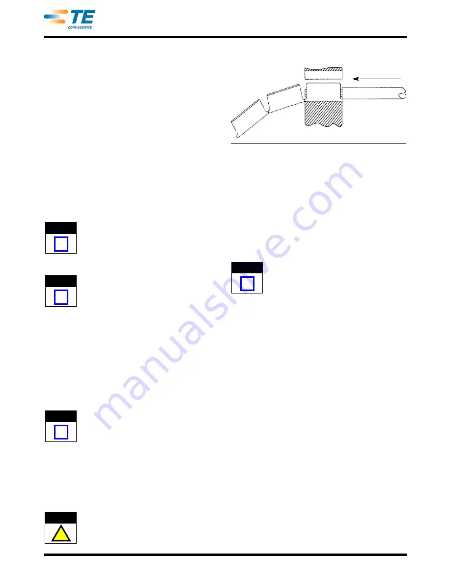
Wire Pin Shown in Strip Form
Wire Inserted in
This Direction
Figure 2
NOTE
i
4. Insert stripped wire into wire pin. See Figure 2.
5. Holding the wire in place, squeeze tool handles
together until ratchet releases. Allow tool handles to
open and remove the crimped contact.
6. Break the crimped contact free from the rest of
the strip by bending the contact back and forth.
7. Check the contacts crimp height as described in
Section 5, CRIMP HEIGHT INSPECTION. If
necessary, adjust the crimp height as described in
Section 6, CRIMP HEIGHT ADJUSTMENT.
Damaged wire pins should not be used. If damaged
wire pins are evident, they should be replaced with
new ones.
5. CRIMP HEIGHT INSPECTION
Crimp height inspection is performed using a
micrometer with a modified anvil, commonly referred
to as a crimp height comparator. Refer to instruction
sheet 408-7424 for detailed information on obtaining
and using a crimp height comparator.
Proceed as follows:
1. Refer to Figure 1 and select a wire (maximum
size) for each crimp section listed.
2. Refer to Section 4, CRIMPING PROCEDURE,
and crimp the contact(s) accordingly.
3. Using the crimp height comparator, measure the
wire barrel crimp height listed in Figure 3. If the
crimp height conforms to that shown in the table,
the tool is considered dimensionally correct. If not,
the tool must be adjusted. Refer to Section 6,
CRIMP HEIGHT ADJUSTMENT.


