background image

408-1261 

Rev

 L


of 19


Tool handles are colored yellow to correspond to the color code of the product. Each tool produces a dot code 
(one dot) on the crimp to correspond to the given wire size range. Refer to Figure 3. 

Figure 3: Product color code 


PIDG terminals 

PLASTI-GRIP terminal 

PIDG butt splice 

Spare wire cap 

Color stripe on heavy duty and radiation resistant 

Three equally space color stripes on insulation restricting 

Color stripe on heavy duty 

Color stripe on radiation resistant 

Color of insulation 


Summary of Contents for 59239-4

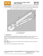
Page 1: ...ns A wide selection of powered application equipment is available for extended use production operations Figure 1 Heavy Head Hand Tools 59239 4 59239 8 59287 2 and 525692 1 304 8 12 00 approximate 2 76 2 3 00 approximate 1 Introduction Heavy Head Hand Tools HHHT 525692 59239 4 59239 8 and 59287 2 are the tool and die set shown in Figure 1 These tools are designed to crimp the product listed in Tab...

Page 2: ...uty PIDG insulation restring nylon terminal Yellow with 3 yellow stripes Stranded copper 12 2 41 5 08 095 200 Yellow with 3 brown stripes 10 3 02 5 08 119 200 PIDG radiation resistant terminal and splice Natural with yellow stripe Stranded copper 12 10 6 60 260 maximum 16 14 heavy duty Spare wire cap 328309 Yellow Stranded copper 12 10 5 33 210 maximum 59287 2 PIDG vinyl and nylon terminal PIDG vi...

Page 3: ...duct After it is engaged the ratchet does not release until the handles have been fully closed When closed the crimping dies form a crimping chamber with two sections an insulation barrel section and a wire barrel section The insulation barrel section crimps the insulation barrel of the product onto the wire insulation Simultaneously the wire barrel section crimps the wire barrel of the product on...

Page 4: ...espond to the given wire size range Refer to Figure 3 Figure 3 Product color code 1 PIDG terminals 2 PLASTI GRIP terminal 3 PIDG butt splice 4 Spare wire cap 5 Color stripe on heavy duty and radiation resistant 6 Three equally space color stripes on insulation restricting 7 Color stripe on heavy duty 8 Color stripe on radiation resistant 9 Color of insulation ...

Page 5: ...ick or damage the wire conductors CAUTION Do not use wire with nicked or missing conductors Figure 4 Wire strip length Table 2 Strip length by product Product Strip length PIDG vinyl and nylon terminal PLASTI GRIP terminal PIDG radiation resistant terminal 7 94 8 73 312 344 PIDG insulation restricting nylon terminal 9 65 10 4 380 410 PIDG vinyl and nylon splice PIDG radiation resistant splice Spar...

Page 6: ...er so that the wire barrel butts against the locator Figure 6 Figure 6 Positioning the terminal 1 Wire barrel against locator 2 End of wire conductors against locator 3 Locator 4 Close the tool handles until the terminal is held firmly in place Do not deform the terminal 5 Insert a properly stripped wire into the terminal wire barrel until the end of the wire conductor s butts against the locator ...

Page 7: ... crimping chamber so that window indentation of the splice rests over the locator Figure 8 Figure 8 Positioning the butt splice 1 End of wire conductors against splice wire stop 2 Locator depressed 3 Splice window indentation over locator 3 Close the tool handles until the splice is held firmly in place Do not deform the splice 4 Insert a properly stripped wire into the wire barrel of the splice u...

Page 8: ...serted in the crimping chamber 3 Depress the locator so that the end of the spare wire cap rests against the recessed surface of the locator Figure 10 Figure 10 Positioning the spare wire cap 1 Wire conductors bottomed in spare wire cap 2 End of spare wire cap against recessed surface of locator 3 Locator depressed 4 Insulation pin in position 3 4 Close the tool handles until the spare wire cap is...

Page 9: ...in range stamped under terminal tongue 6 Dot code one dot is present 7 Wire insulation does not enter wire barrel 8 No nicked or missing conductor strands 9 End of conductor butts against wire stop Figure 12 Features of a poor crimp terminal 1 Nicked or missing conductor strands 2 Crimp not centered on wire barrel terminal was not against locator 3 End of conductor not flush with or extending beyo...

Page 10: ...ation wrong tool or splice or damaged dies 9 End of conductor not flush with or extending beyond end of terminal wire barrel check strip length 10 Wrong color code and dot code combination 11 Wire insulation is extruded insulation crimp is too tight 4 3 PIDG insulation restricting terminal Inspect the crimp for the features shown in Figure 14 Do not use a terminal that has any of the features of a...

Page 11: ...de and tool combination 5 Correct wire size 6 Full width of crimp is over wire barrel of cap 7 Wire insulation does not enter wire barrel 8 No nicked or missing conductor strands 9 End of conductor is bottomed in cap 10 Part of crimp is off end of wire barrel cap was not bottomed in recess of locator 11 Nicked or missing conductor strands 12 End of conductor is not bottomed in cap 13 Wrong wire si...

Page 12: ...al or splice into the crimping chamber as described in section 3 3 Insert an unstripped wire into only the insulation barrel of the terminal or splice 4 Close the tool handles until the ratchet releases 5 Release the tool handles and allow the handles to open fully Remove the crimped terminal or splice 6 Check the insulation barrel crimp by bending the wire back and forth once The terminal or spli...

Page 13: ... the dies or tool Ensure that the retaining pins are in place and secured with retaining rings Protect all pins pivot points and bearing surfaces with a thin coat of any good SAE 20 motor oil Do not oil excessively When the tool is not in use keep the handles closed to prevent objects from becoming lodged in the dies Remove all lubrication and accumulated film by immersing the tool with handles pa...

Page 14: ... the tool handles until the ratchet releases and then allow them to open freely If they do not open quickly and fully the spring is defective and must be replaced Refer to section 7 Replacement and repair NOTE Some tools do not have handle return springs This inspection does not apply to those tools Inspect the tool and dies on a regular basis to ensure that they are not worn or damaged Make sure ...

Page 15: ...or wire barrel section of crimping chamber 1 Die closure configuration 2 GO element dimension 3 NO GO element dimension 4 50 8 2 0 minimum typical Figure 18 Recommended plug gage design for insulation barrel section of crimping chamber 1 Die closure configuration 2 6 35 250 minimum typical 3 6 35 0 13 250 005 4 GO dimension 5 NO GO dimension Table 5 Gage element dimensions Section of crimping cham...

Page 16: ...tom and hold in this position Do not force beyond initial contact 4 Press and hold the locator down 5 Gage the wire barrel section of the crimping chamber by gently inserting the GO and NO GO elements as shown in Figure 19 Do not use force The GO element must pass completely through the crimping chamber The NO GO element can begin entry but must not pass through the crimping chamber Figure 19 Gagi...

Page 17: ...ool for evaluation and repair See section 6 Replacement and repair 6 5 Inspecting the ratchet Check the ratchet to ensure that the ratchet does not release prematurely allowing the dies to open before they have fully bottomed Proceed as follows 1 Remove traces of oil or dirt from the bottoming surfaces of the dies 2 Obtain a 0 025 mm 001 in shim that is suitable for checking the clearance between ...

Page 18: ...Quantity per tool 1 300388 Retaining pin 2 2 21045 3 525108 Retaining ring 4 3 300389 Retaining pin 1 4 21045 6 Retaining ring 2 5 303848 2 Adjustment pin assembly 1 6 306110 9 306110 4 306110 9 Stop locator 1 7 5 21028 7 Pin 1 8 7 59683 6 Spring 1 9 6 306131 4 Screw 2 10 306106 2 45891 8 306106 2 Stationary die insulation 1 11 306107 2 45888 7 306107 2 Moving die insulation 1 12 21028 4 21028 5 2...

Page 19: ... TE link at the top of the page Call 800 522 6752 Write to CUSTOMER SERVICE 038 035 TE CONNECTIVITY CORPORATION PO BOX 3608 HARRISBURG PA 17105 3608 For customer repair services call 800 522 6752 8 Revision summary Since the last revision of this document the following changes were made Reformatted and edited to conform to the current standard for instruction sheets ...

Reviews: