


408-1261
Rev
L
15
of 19
6.4 Gaging the crimping chamber
This inspection requires the use of plug gages conforming to the dimensions listed in Table 5. TE Connectivity
does not manufacture or market these gages. For additional information regarding the use of plug gages, refer
to instruction sheet
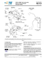
Figure 17: Recommended plug gage design for wire barrel section of crimping chamber
1
Die closure configuration
2
GO element dimension
3
NO GO element dimension
4
50.8 [2.0] minimum (typical)
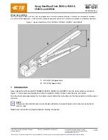
Figure 18: Recommended plug gage design for insulation barrel section of crimping chamber
1
Die closure configuration
2
6.35 [.250] minimum (typical)
3
6.35 ± 0.13 [.250 ± .005]
4
GO dimension
5
NO GO dimension
Table 5: Gage element dimensions
Section of crimping chamber
GO element
NO GO element
Wire barrel
4.293-4.300 [.1690-.1693] 4.442-4.445 [.1749-.1750]
Insulation barrel
1.626-1.633 [.0640-.0643] 2.131-2.134 [.0839-.0840]