TE Technology TC-24-10 Instruction Manual Download Page 2


General Safety Warnings 

This  manual  is  available  in  English  only.  It  must  be  read  and  followed  carefully  before  installation  and 

operation.  


THE  LATEST  REVISION  OF  THIS  MANUAL  IS  AVAILABLE  AT 

www.tetech.com

.  Verify  that  you  are 

using the latest revision available. 


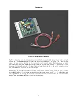
The TC-24-10 should not be used as a toy, or serious injury could result. The TC-24-10 should only 
be  used  for  its  intended  purpose  of  providing  temperature  control  of 

TE  Technology’s 

thermoelectric  devices  only.  The  controller  is  intended  for  light  industrial,  laboratory,  or  similar 
use. It is not intended for household use or medical use. 


Do not use in an explosive or potentially explosive environment. 


Do not use the TC-24-10 to control capacitive or inductive loads or the controller could be damaged 
and/or overheat. Examples of capacitive or inductive loads include but are not limited to motors, 
fans, filters, and solenoids. 


Do  not  allow  the  electrical  connections  on  the  printed  circuit  board  to  touch  any  electrically 
conductive surfaces. 


Do not operate in an environment where the controller could come in contact with condensation, 
water, metal shavings, dirt or other contaminants, or electrically conductive materials. 


Use  ESD  (Electro  Static  Discharge)  protection  when  coming  in  contact  with  electrical  connections 
or components on the controller. 


Do not touch any of the electrical connections or components of the TC-24-10 while the controller 
is energized. Doing so can disrupt the function of the controller. 


Do not use if the controller has been damaged in any way.  


Only qualified technicians should install and operate this controller with the appropriate personal 
protective quipment. 


Improper  tuning  of  this  temperature  controller  can  lead  to  excessive  thermal  cycling  and/or 
overheating of the thermoelectric device, either of which are known to reduce the lifetime of any 
thermoelectric  device.    Care  should  be  taken  to  prevent  the  temperature  of  the  thermoelectric 
device  from  going  beyond  the  range  specified  by  the  device  manufacturer.    Care  should  also  be 
taken  so  that  any  thermal  cycling  of  the  thermoelectric  device  is  a  result  of  changes  in  the 

controller’s set

-point temperature and not instability at a given set point due to improper selection 

of the tuning variables. 


The  temperature  controller  base  underneath  the  transistor-mounting  area  could  exceed  60  °C 
under normal operation. Use caution! Protect against accidental contact with hot surfaces. 


Use protection devices to prevent hazardous conditions and/or damage to equipment. 


Each power input that is used with the controller must be fused separately. Alternatively, a power 
supply with integral over-current protection may be used if it is appropriately sized for protecting 
the controller/TE device. 


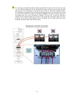
WP5 (+ power in) and WP1 (+ load output) are connected to each other inside the controller. When 
WP5  is  energized  a  voltage  will  be  present  on  WP1,  even  if  the  output  is  off  or  the  controller  is 
being used with two power supplies. 

Summary of Contents for TC-24-10

Page 1: ...c Cooler Temperature Controller October 16 2015 Drawing 3170 Rev I 1590 Keane Drive Phone 231 929 3966 Traverse City MI 49696 USA Fax 231 929 4163 Web www tetech com e mail cool tetech com All Materials Copyright 2012 TE Technology Inc TETECHNOLOGY INC ...

Page 2: ... the TC 24 10 while the controller is energized Doing so can disrupt the function of the controller Do not use if the controller has been damaged in any way Only qualified technicians should install and operate this controller with the appropriate personal protective quipment Improper tuning of this temperature controller can lead to excessive thermal cycling and or overheating of the thermoelectr...

Page 3: ...e A copy of the TCA Instruction manual can also be sent via regular mail upon request TE Technology Inc does not make any warranty expressed or implied that the use or operation of the equipment will be functional or effective if the equipment is not installed and used in accordance with this manual TE Technology Inc shall not be liable and Purchaser shall defend hold harmless and indemnify TE Tec...

Page 4: ...4 3 0 Controller Tuning 15 Controller Wiring Diagram One Power Supply Setup 17 Controller Wiring Diagram Two Power Supplies Setup 18 Mechanical Package Drawing 19 Temperature vs Sensor Potentiometer Voltage graphs 20 Temperature vs Sensor Potentiometer Voltage table 21 Thermistor Styles for TC 24 10 22 ...

Page 5: ...e the TC 24 10 lacks some of the features found in our more sophisticated controllers such as having a display or being able to directly interface with a computer its low cost makes it ideal for projects that have limited budgets Mechanically the controller s printed circuit board is mounted to a metal bracket It can be mounted either horizontally or vertically The controller can operate in ambien...

Page 6: ...ment 0 to 2 55 repeats per minute Output Square wave 1000 Hz Pulse width modulated Operating temperature range 0 C to 50 C ambient with aluminum mounting plate in a vertical position allowing free air convection 0 25 inch quick connect terminals for power cooler and thermistor connections RoHS compliant The controller s operating temperature range is 0 C to 50 C ambient The range can be extended t...

Page 7: ...ot usually required Multiple Control Configurations The controller can be used with either one power supply for powering the controller electronics and the TE device together or with two power supplies for powering the controller electronics and TE device independently Whether the controller is configured to use one or two power supplies the TE device should not be allowed to draw more than 10 A a...

Page 8: ...aximum allowable ambient temperature for the controller is 50 C Furthermore the maximum allowable temperature of the controller base underneath the transistor mounting area is 90 C Furthermore the controller might need additional heat sinking depending on ambient conditions and how much current is being drawn by the TE device Note See Controller Wiring Diagram One Power Supply Setup or Controller ...

Page 9: ...ing the controller and the TE device together the power supply input voltage is passed directly through the controller to the TE device during the ON pulse The user should choose an input voltage that is required for the TE device and yet is also 9 V but 26 V The controller could be damaged if operated outside this voltage range When using two power supplies the controller input power supply must ...

Page 10: ...ment where a hazardous condition can be detected These protection devices should de energize the TC 24 10 the load and as necessary other related secondary equipment It is further recommended that such devices require the user to remove and correct the root cause of a fault before allowing the TC 24 10 the load and related equipment to be re energized Protection devices should include but are not ...

Page 11: ... to 40 V to the controller for powering the module Negative power supply terminal to WP6 NOTE both power supplies must connect their negative terminals to WP6 c Do NOT connect the TE device negative terminal to the controller at this time d See the Controller Wiring Diagram Two Power Supplies Setup for further details 1 5 Turn on the power supply to the controller and adjust the temperature set po...

Page 12: ... be used for the TE device b Connect the negative terminal of ONLY the TE device to WP2 c Verify that JP1 is shorted that is a jumper is installed which is the factory default HEATING MODE One Power Supply Operation a Connect the positive terminal of ONLY the TE device to WP2 b Connect the negative terminal of ONLY the TE device to WP1 c Verify that JP1 is open that is no jumper is installed Two P...

Page 13: ... is applicable only when applying power directly from the power supply When using the TCA with the temperature controller the jumpers MUST be removed so that the controller is controlling power only to the thermoelectric modules There must be no electrical connection between the fans and the modules fans must be connected directly to the power supply not to the controller The controller will be da...

Page 14: ...width is set to 5 C The controller power starts to proportionally decrease as the sensor temperature cools below 12 5 C The power will be reduced to 50 when the sensor is at 10 0 C Finally the power will be at 0 when the sensor is at 7 5 C Of course this example presumes that the cooler would have enough capacity to cool to 7 5 C If the bandwidth is set too narrow the temperature will oscillate ar...

Page 15: ...tentiometer has been adjusted to the maximum clockwise or maximum counterclockwise position the adjustment pawl will ratchet on the screw driven gear making a slight clicking sound 3 1 Set the Integral Rate Potentiometer R8 to zero by adjusting it to maximum counterclockwise 3 2 Set the Proportional Bandwidth Potentiometer R2 to 5 C by adjusting it to maximum clockwise 3 3 Set the desired control ...

Page 16: ...ber of turns on the Integral Rate Potentiometer __________________ from maximum counterclockwise Additional systems with the same thermodynamic properties will operate using the Potentiometer settings listed above Tuning Example A Suppose that 16 counterclockwise turns of the Proportional Bandwidth Potentiometer R2 were required to just sustain a temperature oscillation This corresponds to a propo...

Page 17: ...als When one or more external fans are used on the TE device these should be wired directly to a fixed voltage power supply for constant operation When connecting the controller to a TE Technology Thermoelectric Cooling Assembly TCA verify that the electrical jumpers shorts located on the TCA terminal block are installed removed per the TCA operating manual before powering the controller THERMISTO...

Page 18: ...s Setup THERMISTOR DC POWER SUPPLY WP1 WP5 WP6 WP2 WP4 WP3 R8 R7 JP1 R2 DC POWER SUPPLY 9 V 26 V 150 mA 0 V 40 V 10 A maximum TE DEVICE shown in cooling mode CONNECT POWER SUPPLY GROUNDS TOGETHER AT WP6 FUSE THERMOSTAT AND OTHER PROTECTIVE DEVICES ...

Page 19: ...ing PROPORTIONAL BANDWIDTH POTENTIOMETER HEAT COOL MODE JUMPER SET TEMPERATURE POTENTIOMETER INTEGRAL RATE POTENTIOMETER 45 7 38 1 69 8 50 8 63 5 3 96 Ø3 96 NOTE ALL DIMENSIONS IN MILLIMETERS WP5 WP1 WP6 WP2 WP4 WP3 R7 JP1 R2 R8 ...

Page 20: ... 0 8 1 2 1 6 2 0 2 4 2 8 3 2 3 6 4 0 4 4 4 8 5 2 20 12 4 4 12 20 28 36 44 52 60 68 76 84 92 100 Temperature C Voltage V Potentiometer Voltage Vs Set point Temperature 0 0 0 4 0 8 1 2 1 6 2 0 2 4 2 8 3 2 3 6 4 0 4 4 4 8 5 2 20 12 4 4 12 20 28 36 44 52 60 68 76 84 92 100 Temperature C Voltage V ...

Page 21: ... 40 4 17 61 1 76 1 63 1 4 38 4 13 62 1 72 1 58 2 4 35 4 08 63 1 68 1 54 3 4 32 4 04 64 1 64 1 50 4 4 29 4 00 65 1 60 1 46 5 4 26 3 96 66 1 56 1 42 6 4 23 3 92 67 1 52 1 38 7 4 19 3 88 68 1 49 1 33 8 4 16 3 83 69 1 45 1 29 9 4 12 3 79 70 1 42 1 25 10 4 09 3 75 71 1 38 1 21 11 4 05 3 71 72 1 35 1 17 12 4 02 3 67 73 1 32 1 13 13 3 98 3 63 74 1 28 1 08 14 3 94 3 58 75 1 25 1 04 15 3 90 3 54 76 1 22 1 ...

Page 22: ...ions in millimeters Some styles do not include fast on terminals 25 4 3 18 6 35 SQ 3 94 Ø3 61 THRU 914 4 2 26 AWG STRANDED WIRE UL1430 IRRADIATED CROSS LINKED PVC INSULATION ORANGE ALUMINUM BLOCK EPOXY FILL NOTE ALL DIMENSIONS IN MILLIMETERS MP 2444 MP 2444 MP 3238 MP 3238 MP 2542 MP 2542 MP 2542 ...

Page 23: ...0 7976 61 3590 82 1761 1 51750 20 18751 41 7662 62 3464 83 1705 0 49157 21 17923 42 7362 63 3343 84 1652 20 146735 1 46709 22 17136 43 7075 64 3227 85 1601 19 138447 2 44397 23 16388 44 6801 65 3115 86 1551 18 130677 3 42213 24 15676 45 6539 66 3008 87 1503 17 123390 4 40150 25 15000 46 6289 67 2905 88 1457 16 116554 5 38199 26 14356 47 6049 68 2806 89 1412 15 110138 6 36354 27 13744 48 5820 69 27...

Reviews: