background image

8

8

Mounting

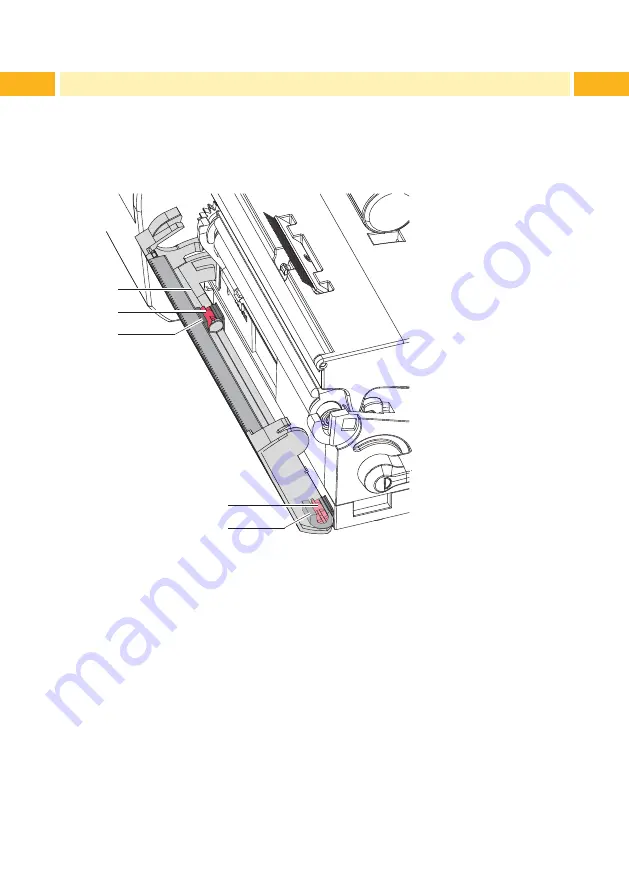
2.1  Removing the Tear-off Plate

Before mounting the perforator the tear-off plate mounted on the printer must 

be removed.

2

1

3

2
3

Figure 1  Removing the tear-off plate


Gently pull the Tear off plate forward (1), pull the axles (2) of the tear-off 

plate out of the holders (3) and remove the tear-off plate.

Summary of Contents for T2212

Page 1: ...Operator s Manual T2212 PRINTER PERFORATOR...

Page 2: ...ous written authorization by TE Connectivity Trademark Windows is a registered trademark of the Microsoft Corporation Editor Regarding questions or comments please contact TE Connectivity Topicality D...

Page 3: ...g 8 2 1 Removing the Tear off Plate 8 2 2 Mounting the Perforator 9 3 Operation 10 3 1 Loading Material 10 3 2 Reference to the Programming 11 3 3 Standard Operation 12 4 Printer Configuration 13 5 Cl...

Page 4: ...t could lead to injuries or material damage Attention Draws attention to possible dangers material damage or loss of quality i Note Gives you tips They make a working sequence easier or draw attention...

Page 5: ...ice is manufactured in accordance with the current technological status and the recognized safety rules However danger to the life and limb of the user or third parties and or damage to the device and...

Page 6: ...e can also endanger operational safety Always have service work done in a qualified workshop where the personnel have the technical knowledge and tools required to do the necessary work Technical Supp...

Page 7: ...Weight cardboard g m 60 240 Thickness mm 0 05 1 1 Cutting length mm 10 Cut frequency 1 min 200 Power Supply Perforator connector of the printer Attention The minimum cut length is depending on the med...

Page 8: ...ing the perforator the tear off plate mounted on the printer must be removed 2 1 3 2 3 Figure 1 Removing the tear off plate X X Gently pull the Tear off plate forward 1 pull the axles 2 of the tear of...

Page 9: ...1 2 3 4 4 3 5 Figure 2 Mounting the perforator 1 Put snap arm 2 of the perforator 5 into the guide 1 2 Push the axles 3 into the holders 4 3 Gently push the perforator unit forward 5 so that it snaps...

Page 10: ...Printhead and drive roller so that the front edge reaches through the perforator unit 2 1 Figure 3 Guiding labels and tube into the perforator unit X X Guide labels or tube 2 into slot 1 then engage...

Page 11: ...ess For synchronization the media will be moved forward and cut off That synchronization is not necessary when the printhead was not opened between print jobs even if the printer was powered off betwe...

Page 12: ...re are added together for execution Cut Parameters X X Start menu X X Select Setup Cutting Parameter Meaning Default Cut position Offset of the cut position relative to the rear label edge The setting...

Page 13: ...the next label is not yet completely prepared when peeling off cutting the current label Otherwise the second label is pushed on and completed after removal of the first label without backfeeding sma...

Page 14: ...may accumulate on the blades If operating in backfeed mode such remains of adhesive may be deposited on the drive roller as well X X Clean the drive roller and the perforator blades often 1 2 3 4 Figu...

Page 15: ...ith label remover and a soft cloth X X If necessary replace the blades X X Push the lower blade down into the guides 11 X X If necessary put the springs 12 back into the spring retainers 13 X X To re...

Page 16: ...Perforator CE EU C of C EU Declaration of Conformity 6 2 FCC NOTE This equipment has been tested and found to comply with the limits for a Class A digital device pursuant to Part 15 of the FCC Rules...

Reviews: