Tyco Electronics Corporation
300 Constitutional Drive
Menlo Park, CA 94025 USA
No: RPIP-824-00
Rev: F
Date: April 28, 2006
Page: 10 of 11
© 2005-2006 Tyco Electronics Corporation. All rights reserved.
Unless otherwise specified dimensions are in millimeters [Inches dimensions are in between brackets]
If this document is printed it becomes uncontrolled. Check for the latest revision.
4.5.2 Assembly
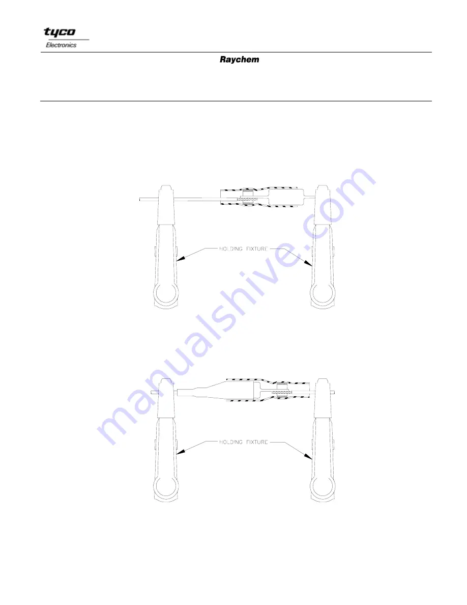
1. Overlap the exposed conductor and the component pin and position the CWT-200X-A
or B-155-200X-A sub-assembly so that the solder preform is centered over the conductors.
2. Use a holder to keep the wire and component aligned during heating.
3. Heat solder preform until it melts and forms a fillet between the conductors.
4. Overlap the other exposed conductor and component pin and position the CWT-200X-B
or B-155-200X-B sub-assembly so the solder preform is centered over the conductors.
5. Use a holder to keep the wire and component aligned during heating.
6. Heat solder preform until it melts and forms a fillet between the conductors.


