114-151049
Rev A
5
of 11
D. Modification
NOTES:
1)
Modifications include but are not limited to the following list.
2)
Modifications listed are for reference only and may not be available for every arrangement.
Modification
Description
A004
Pins on PCB side
C023
M5 Threaded Inserts on Flange
CG01
M5 Threaded Inserts on Flange
Pins on outside rows are Gold, All other Tin
G002
Pins on outside rows are Gold, All other Tin
3.4.
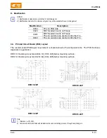
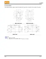
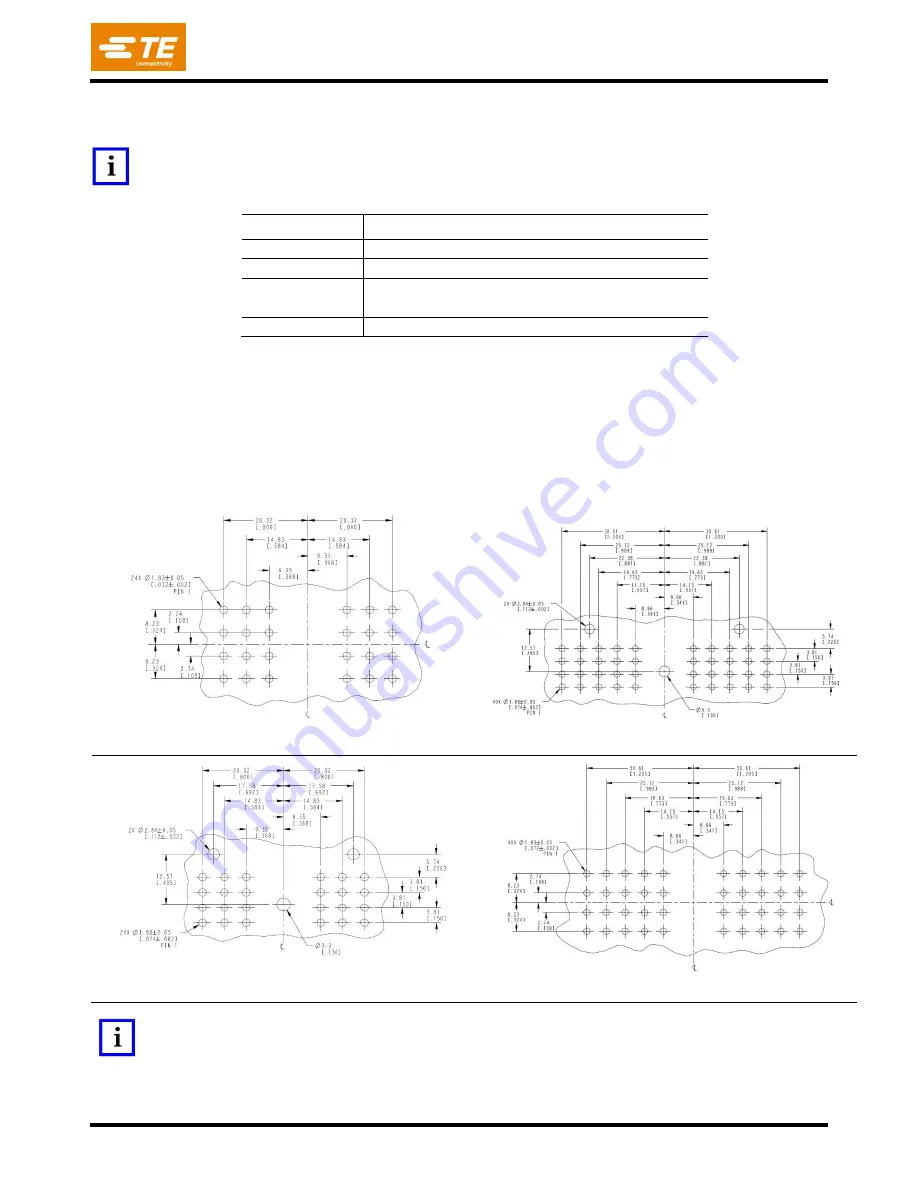
Printed Circuit Board (PCB) Layout
The recommended PCB layout requirement is shown below for the component side. The PCB thickness
depends on application.
DRC10: Header pins extend 4.83±.13 [.190±.005] below mounting surface.
DRC13: Header pins extend 3.20±.64 [.126±.025] below mounting surface.
DRC10-24P
DRC10-40P
DRC13-24P
DRC13-40P
Note:
1)
Tolerance: ±.05 [.002].
2)
Customer to determine finished hole diameter based on soldering process, through hole plating, etc.


